Check patentability & draft patents in minutes with Patsnap Eureka AI!

Method for predetermining a motion state of a drive shaft of an internal combustion engine

a technology of drive shaft and motion state, which is applied in the direction of analogue computers, structural/machine measurement, analog and hybrid computing, etc., can solve the problems of difficult alignment of the circumferential speed of toothed ring and starting pinion, circumferential speed, and the ability of the starting pinion to seldom, or not at all, to engage the starting pinion

Inactive Publication Date: 2014-08-26
SEG AUTOMOTIVE GERMANY GMBH
View PDF20 Cites 2 Cited by
  • Summary
  • Abstract
  • Description
  • Claims
  • Application Information

AI Technical Summary

Benefits of technology

This method enables more precise and quicker restarts of the internal combustion engine with reduced wear on the starting pinion and toothed ring by accurately predicting motion states and optimizing engagement conditions, independent of engine aging or production variations.

Problems solved by technology

Said rotational speed fluctuations during the macroscopic run-down have the result that the starting pinion can seldom, or not at all, be engaged into the toothed ring in such a manner as to protect the transmission.
The problem here is the adaptation of the circumferential speeds, that is to say substantially the alignment of the circumferential speeds of toothed ring and starting pinion, which is difficult.
Furthermore, an early starting of the starting pinion with high load can have the result that the starting pinion on the one hand cannot at all engage into the toothed ring, instead to some extent “ratcheting” with its teeth against the teeth of the toothed ring, and as a result the starting pinion and its teeth are subjected to considerable wear.
If the starting pinion has however already been engaged slightly into the toothed ring but is already under high torque loading, there is the risk, owing to a possibly only slight degree of overlap of teeth on the toothed ring and teeth on the starting pinion, that the teeth are generally loaded only over a short distance, instead being loaded at said point with a uniform load or tooth load which is too high for said short degree of overlap.
There is the risk here of teeth, or parts of said teeth, breaking away.

Method used


Image

  • Method for predetermining a motion state of a drive shaft of an internal combustion engine
  • Method for predetermining a motion state of a drive shaft of an internal combustion engine
  • Method for predetermining a motion state of a drive shaft of an internal combustion engine

Examples


Embodiment Construction

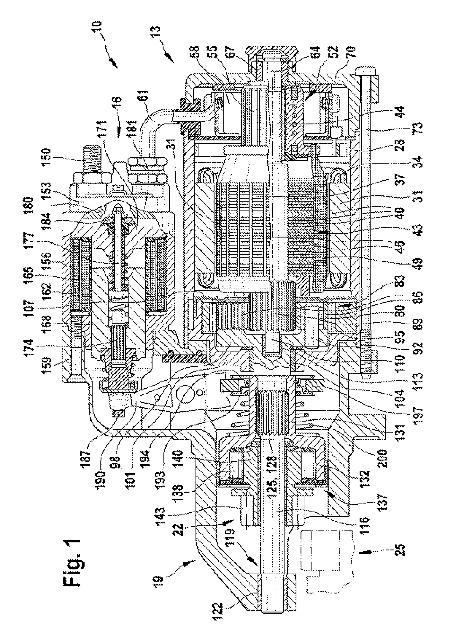
[0023]FIG. 1 shows a starting device 10 in a longitudinal section. Said starting device 10 has for example a starter motor 13 and a pre-engagement actuator 16 (for example relay, starter relay). The starter motor 13 and the electric pre-engagement actuator 16 are fastened to a common drive bearing shield 19. The starter motor 13 serves functionally to drive a starting pinion 22 when it is engaged in the toothed ring 25 of the internal combustion engine (not illustrated here).

[0024]The starter motor 13 has, as a housing, a pole tube 28 which on its inner circumference bears pole shoes 31, around each of which is wound an exciter coil 34. The pole shoes 31 in turn surround an armature 37 which has an armature pack 43 constructed from plates 40 and has an armature coil 49 arranged in grooves 46. The armature pack 43 is pressed onto a driveshaft 44. On that end of the driveshaft 13 which faces away from the starter pinion 22 there is furthermore mounted a commutator 52 which is construc...


PUM


Abstract

The invention relates to a method for predetermining a motion state (BZn+1) of a drive shaft (222) of an internal combustion engine (210) on the basis of previous motion states (BZn, BZn−2) of the drive shaft (222), wherein properties (tn−2, ωn−2) allocated to a first previous motion state (BZn−2) and properties (tn, ωn) allocated to a second previous motion state (BZn) are used and the drive shaft (222) assumes periodically recurring angular positions (φn−2, φn, φn+2; φn−1, φn+1). The invention is characterized in that a future motion state (BZn+1) and the properties (tn−1, φn+1) allocated thereto of the drive shaft (222) are determined in an angular position on the basis of the first evaluated previous motion state (BZn−2) and the second evaluated previous motion state (BZn), wherein the angular position (φn+1) of the determined future motion state (BZn+1)of the drive shaft (222) is not equal to an angular position (φn−2, φn) of the first and second previous motion state (BZn, BZn−2).

Description

BACKGROUND OF THE INVENTION[0001]The invention relates to a method for predetermining a motion state of a driveshaft of an internal combustion engine. Said method, which is performed by means of a controller for start-stop operation of an internal combustion engine in a motor vehicle, serves to realize the so-called engagement upon run-down. Engagement upon run-down means that a starting pinion of a starting device, preferably in the form of a preengaged drive starter, engages into a still-rotating toothed ring of the internal combustion engine. A still-rotating toothed ring of the internal combustion means that the standstill state, that is to say the discontinuance of rotation of the driveshaft of the internal combustion engine, is already planned, intended or has already been initiated. During said run-down, the rotational speed of the driveshaft decreases macroscopically. Considering the run-down of the driveshaft of the internal combustion engine in detail, however, it can be s...

Claims


Application Information

Patent Timeline
Patent Type & Authority Patents(United States)
IPC IPC(8): G01M15/04F02D41/00F02N11/08
CPCF02N11/0855F02D41/0097F02N15/022F02N15/046F02N15/067F02N2200/021F02N2200/022F02N2300/2006F02N2300/2008
Inventor CWIK, MATTHIASROESSLE, MARKUSMAURITZ, EWALDTUMBACK, STEFAN
Owner SEG AUTOMOTIVE GERMANY GMBH
Features
  • R&D
  • Intellectual Property
  • Life Sciences
  • Materials
  • Tech Scout
  • Unparalleled Data Quality
  • Higher Quality Content
  • 60% Fewer Hallucinations
Learn More