Light-emitting device, method of manufacturing light-emitting device, and illumination device
a technology of light-emitting devices and manufacturing methods, which is applied in the direction of lighting support devices, printed circuit components, lighting and heating apparatus, etc., can solve the problems of high labor intensity, large number of steps in the work of boring holes in the substrate, and redundant conductor patterns
- Summary
- Abstract
- Description
- Claims
- Application Information
AI Technical Summary
Benefits of technology
Problems solved by technology
Method used
Image

Examples
first embodiment
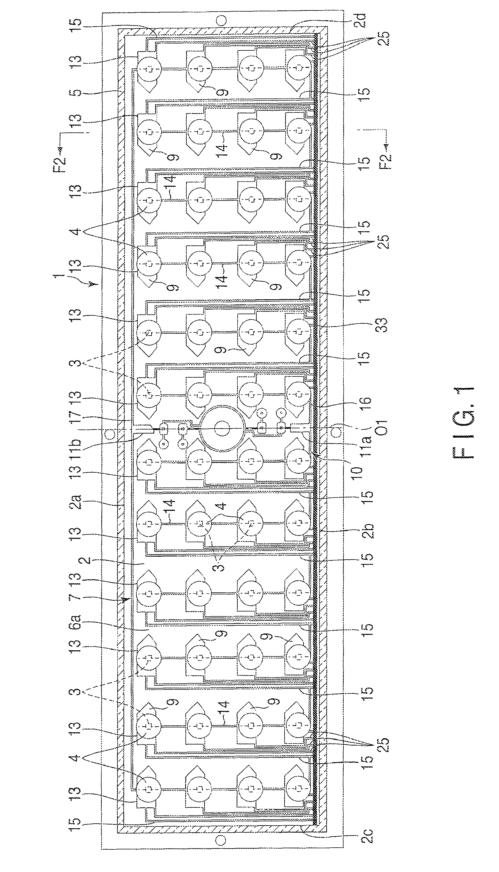
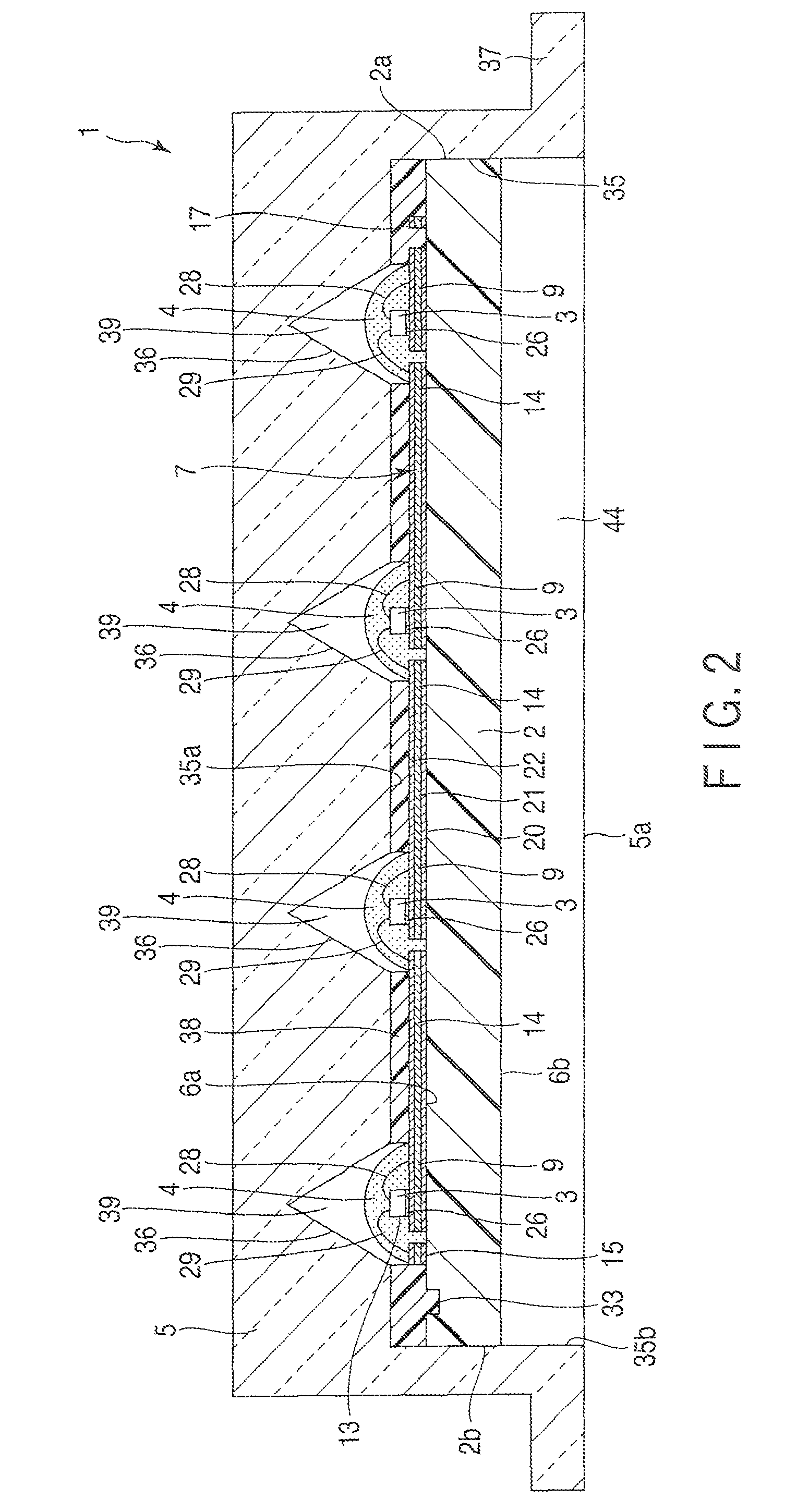
[0035]A first embodiment will be described hereinafter with reference to FIG. 1 to FIG. 10.
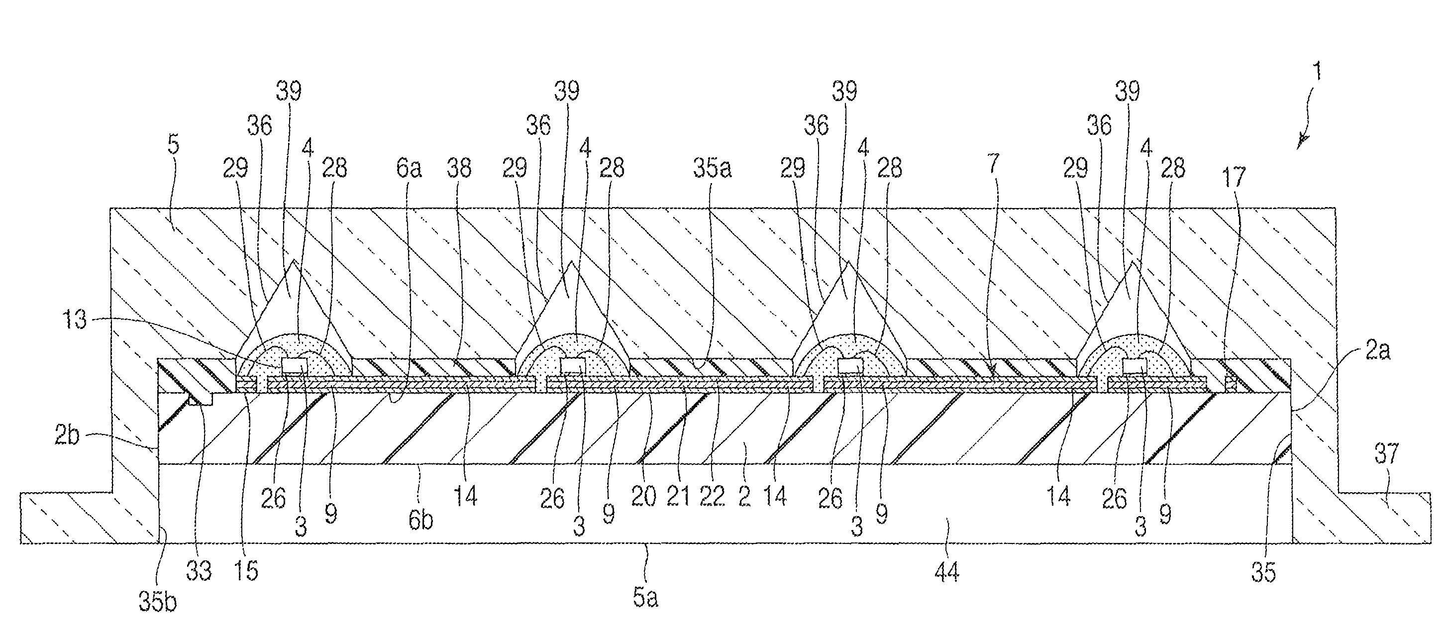
[0036]FIG. 1 to FIG. 8 illustrate a light-emitting device 1 which serves as illumination light source. As illustrated in FIG. 1 and FIG. 2, the light-emitting device 1 comprises a substrate 2, a plurality of light-emitting elements 3, a plurality of sealing members 4, and a protective cover 5.
[0037]The substrate 2 is formed of synthetic resin material, such as glass epoxy resin, which has thermal conductivity lower than that of metal. The material of the substrate 2 is not limited to glass epoxy resin, by other synthetic resin materials or ceramics materials can be used for the substrate 2. Although the substrate 2 is preferably formed of material which has thermal conductivity lower than that of metal, it is possible to adopt a substrate which has a core material formed of metal having excellent thermal conductivity such as aluminum.
[0038]As illustrated in FIG. 1 and FIG. 2, the substrate 2 h...
second embodiment
[0090]FIG. 11 discloses an illumination device 51 according to a second embodiment.
[0091]The illumination device 51 uses three light-emitting devices 1 as light source. The structure of the light-emitting device 1 is the same as that of the first embodiment. In FIG. 11, a protective cover is omitted to show the internal structure of the light-emitting devices 1.
[0092]As illustrated in FIG. 11, the illumination device 51 includes a case 52 which is surface-mounted on the ceiling. The case 52 is an example of a main body of the illumination device 51. The case 52 has an elongated box shape, and has an elongated opening part 53 which is opened downward. The three light-emitting devices 1 and a power supply unit which lights the three light-emitting devices 1 are contained in the case 52. The light-emitting devices 1 are arranged in line along a longitudinal direction of the case 52. The protective cover of each light-emitting device 1 is exposed from the opening part 53 of the case 52 ...
third embodiment
[0094]FIG. 12 to FIG. 18 disclose a light-emitting device 61 according to a third embodiment.
[0095]The light-emitting device 61 which serves as illumination light source comprises a substrate 62, a plurality of light-emitting elements 63, and a pair of sealing members 64a and 64b. The substrate 62 is formed of a synthetic resin material such as glass epoxy resin. The substrate 62 has an elongated shape which has a pair of long sides 62a and 62b, and a pair of short sides 62c and 62d. In addition, the substrate 62 has a first surface 65a, a second surface 65b positioned opposite to the first surface 65a, and an outer peripheral surface 65c which connects the first surface 65a with the second surface 65b. The first and the second surfaces 65a and 65b are flat surfaces. According to the second embodiment, a length of the substrate 62 along the long sides 62a and 62b is 230 mm, and a width of the substrate 62 along the short sides 62c and 62d is 35 mm. In addition, a thickness of the su...
PUM
 Abstract
Description
Claims
Application Information
 - R&D
- Intellectual Property
- Life Sciences
- Materials
- Tech Scout
- Unparalleled Data Quality
- Higher Quality Content
- 60% Fewer Hallucinations
Browse by: Latest US Patents, China's latest patents, Technical Efficacy Thesaurus, Application Domain, Technology Topic, Popular Technical Reports.
© 2025 PatSnap. All rights reserved.Legal|Privacy policy|Modern Slavery Act Transparency Statement|Sitemap|About US| Contact US: help@patsnap.com