Magnetic head for perpendicular magnetic recording including a heater
a perpendicular magnetic and recording head technology, applied in the direction of magnetic recording heads, data recording, instruments, etc., can solve the problems of insufficient reduction of the distance between the surface of the recording medium, inability to achieve sufficient recording density, and inability to allow the end face of the main pole to greatly protrude relative to its neighboring surroundings. to achieve the effect of increasing the amount of protrusion
- Summary
- Abstract
- Description
- Claims
- Application Information
AI Technical Summary
Benefits of technology
Problems solved by technology
Method used
Image

Examples
first embodiment
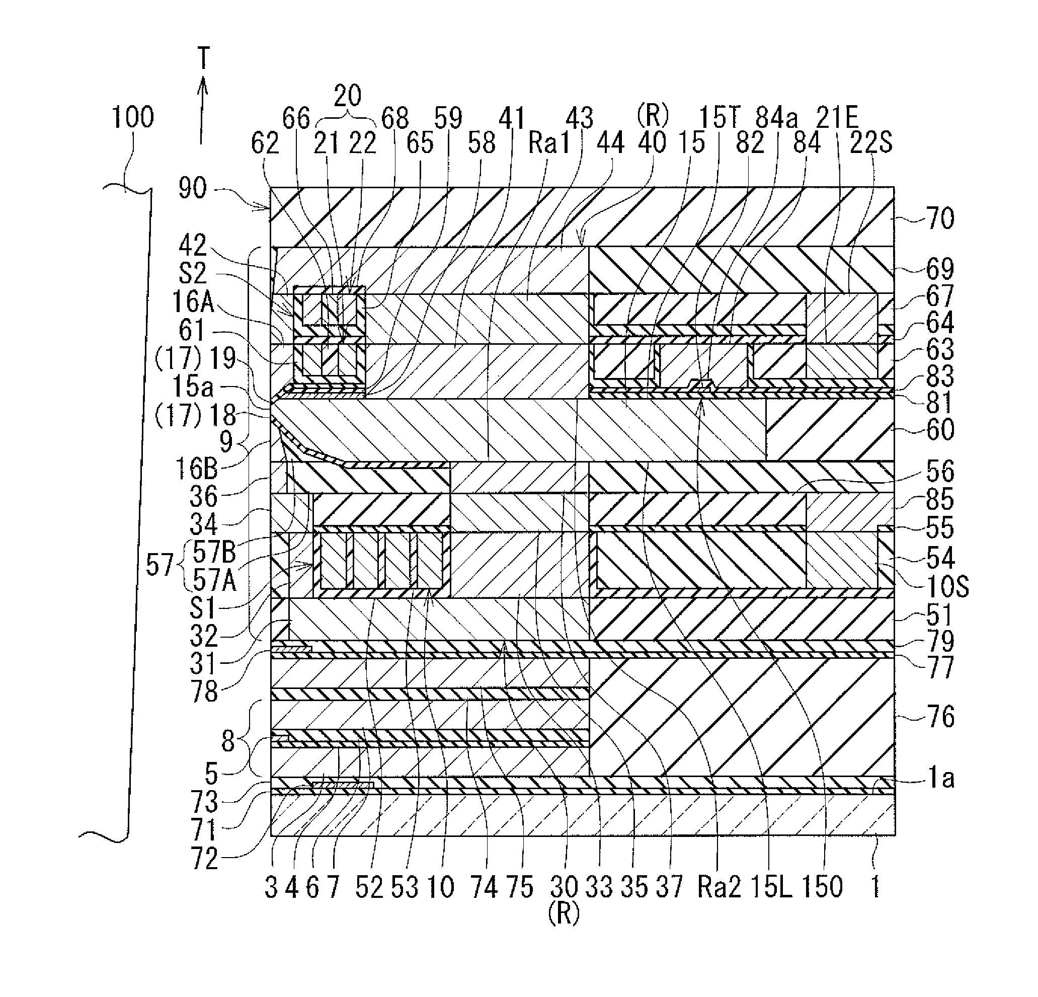
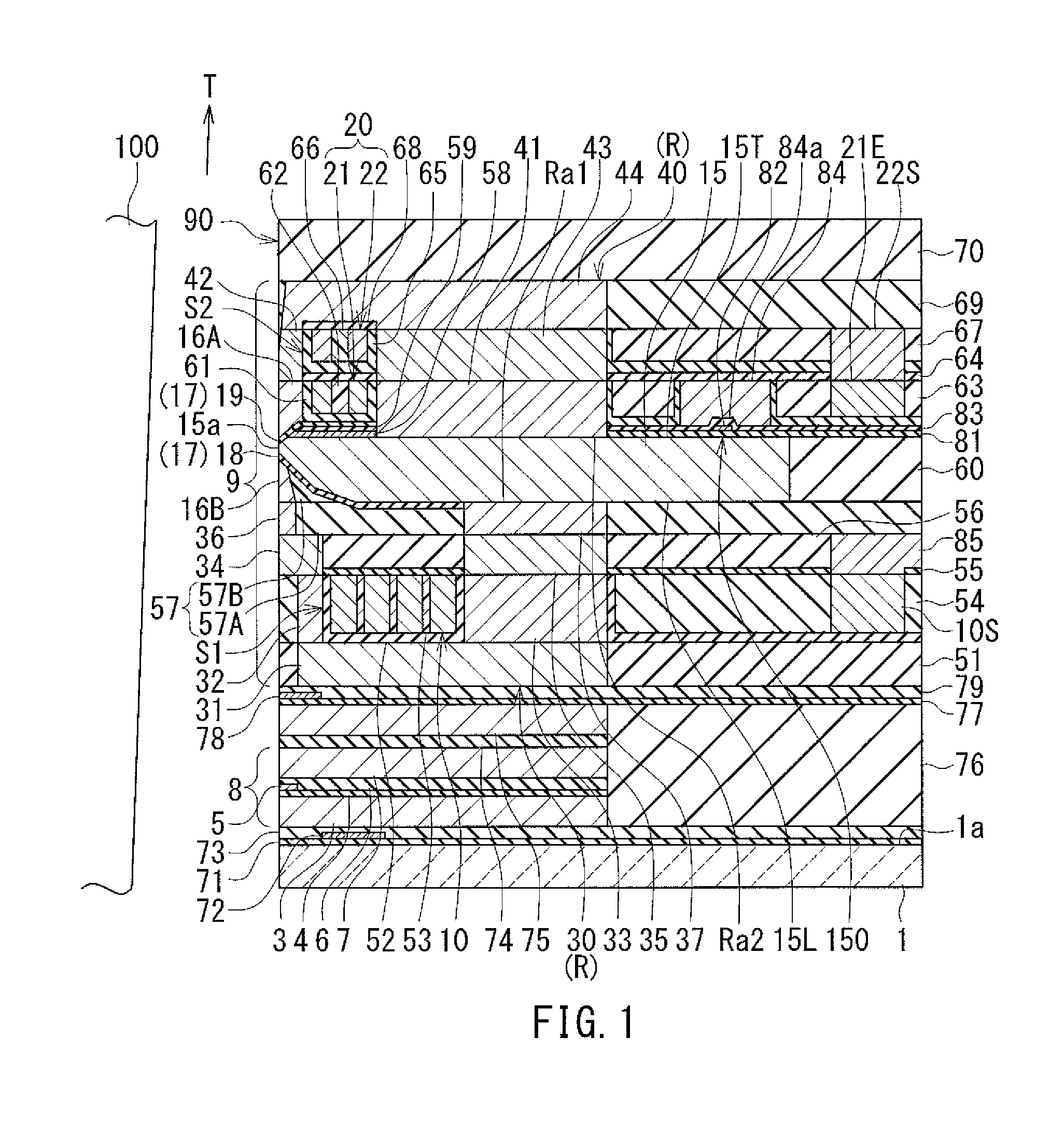
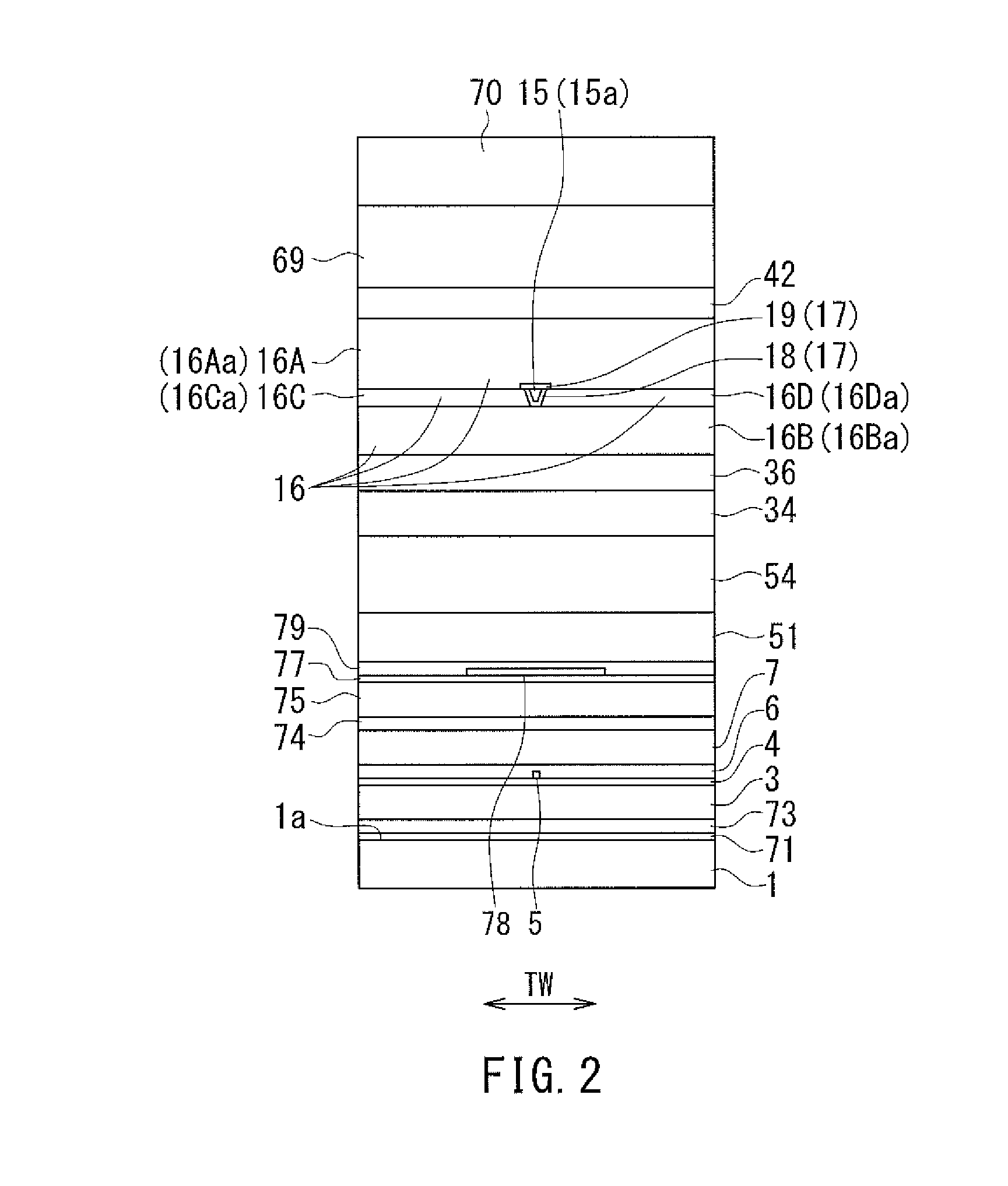
[0048]Preferred embodiments of the present invention will now be described in detail with reference to the drawings. First, reference is made to FIG. 1 to FIG. 5 to describe the configuration of a magnetic head according to a first embodiment of the invention. FIG. 1 is a cross-sectional view showing the magnetic head according to the present embodiment. The arrow with the symbol T in FIG. 1 indicates the direction of travel of a recording medium. FIG. 2 is a front view showing the medium facing surface of the magnetic head according to the present embodiment. FIG. 3 is a plan view showing a first portion of a coil of the magnetic head according to the present embodiment. FIG. 4 is a plan view showing a first layer of a second portion of the coil and a heater of the magnetic head according to the present embodiment. FIG. 5 is a plan view showing a second layer of the second portion of the coil of the magnetic head according to the present embodiment. The arrow with the symbol TW in ...
modification example
[0145]A modification example of the magnetic head according to the present embodiment will now be described with reference to FIG. 9. FIG. 9 is a cross-sectional view showing the modification example of the magnetic head according to the present embodiment. In the modification example, the first portion 10 and the first and second layers 21 and 22 of the second portion 20 of the coil have their respective numbers of turns that are different from those of the example shown in FIG. 1 and FIG. 3 to FIG. 5. In the modification example, the first portion 10 is wound approximately three turns around the magnetic layer 33. The first layer 21 of the second portion 20 is wound approximately one turn around the magnetic layer 41 and the metal portion 84. The second layer 22 of the second portion 20 is wound one turn around the magnetic layer 43. Further, the modification example does not have the insulating layers 62 and 66.
[0146]With increases in frequency of write signals for higher recordi...
second embodiment
[0149]A magnetic head according to a second embodiment of the invention will now be described with reference to FIG. 10 and FIG. 11. FIG. 10 is a cross-sectional view showing the magnetic head according to the present embodiment. FIG. 11 is a plan view showing the first layer of the second portion of the coil and the heater of the present embodiment. In the present embodiment, the positioning of the first layer 21 of the second portion 20 of the coil and the metal portion 84 relative to each other is different from that in first embodiment. In the present embodiment, the first layer 21 is adjacent to the metal portion 84 with the insulating film 61 interposed therebetween when seen not only at the positions on opposite sides in the track width direction TW relative to the main cross section but also at a position on a side of the metal portion 84 opposite to the medium facing surface 90. In the present embodiment, the position of a portion of the inner wall of the innermost turn of ...
PUM
 Abstract
Description
Claims
Application Information
 - R&D
- Intellectual Property
- Life Sciences
- Materials
- Tech Scout
- Unparalleled Data Quality
- Higher Quality Content
- 60% Fewer Hallucinations
Browse by: Latest US Patents, China's latest patents, Technical Efficacy Thesaurus, Application Domain, Technology Topic, Popular Technical Reports.
© 2025 PatSnap. All rights reserved.Legal|Privacy policy|Modern Slavery Act Transparency Statement|Sitemap|About US| Contact US: help@patsnap.com