Check patentability & draft patents in minutes with Patsnap Eureka AI!

Vehicle lighting unit

a technology for vehicles and lighting devices, applied in fixed installation, light and heating equipment, transportation and packaging, etc., can solve the problem of different brightnesses observed through the lenses

Inactive Publication Date: 2014-10-14
STANLEY ELECTRIC CO LTD
View PDF12 Cites 2 Cited by
  • Summary
  • Abstract
  • Description
  • Claims
  • Application Information

AI Technical Summary

Benefits of technology

This configuration ensures that the brightnesses observed through the first and second lenses are substantially matched when viewed from a front perspective, allowing for uniform illumination and effective irradiation of overhead sign regions, while maintaining a compact design with lenses visually recognized as a single light-emitting region.

Problems solved by technology

This causes a problem in that the brightnesses observed through the lenses are different from each other.

Method used


Image

  • Vehicle lighting unit
  • Vehicle lighting unit
  • Vehicle lighting unit

Examples


Embodiment Construction

[0025]A description will now be made below to vehicle lighting units of the presently disclosed subject matter with reference to the accompanying drawings in accordance with exemplary embodiments.

[0026]In the present specification, it should be noted that the upper (upward), lower (downward), left, right, back (rearward), and front (forward) directions are based on a typical posture of a vehicle body to which the vehicle lighting unit is installed unless otherwise specified.

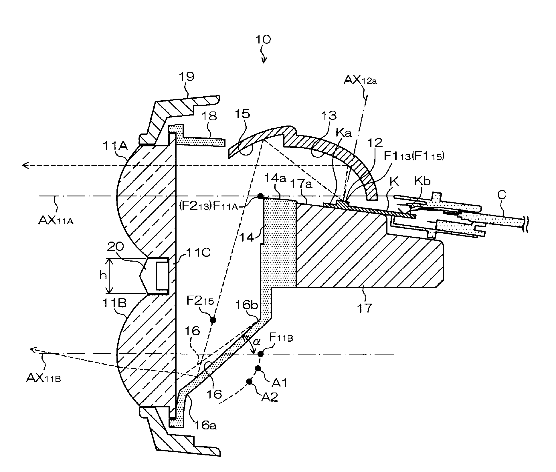
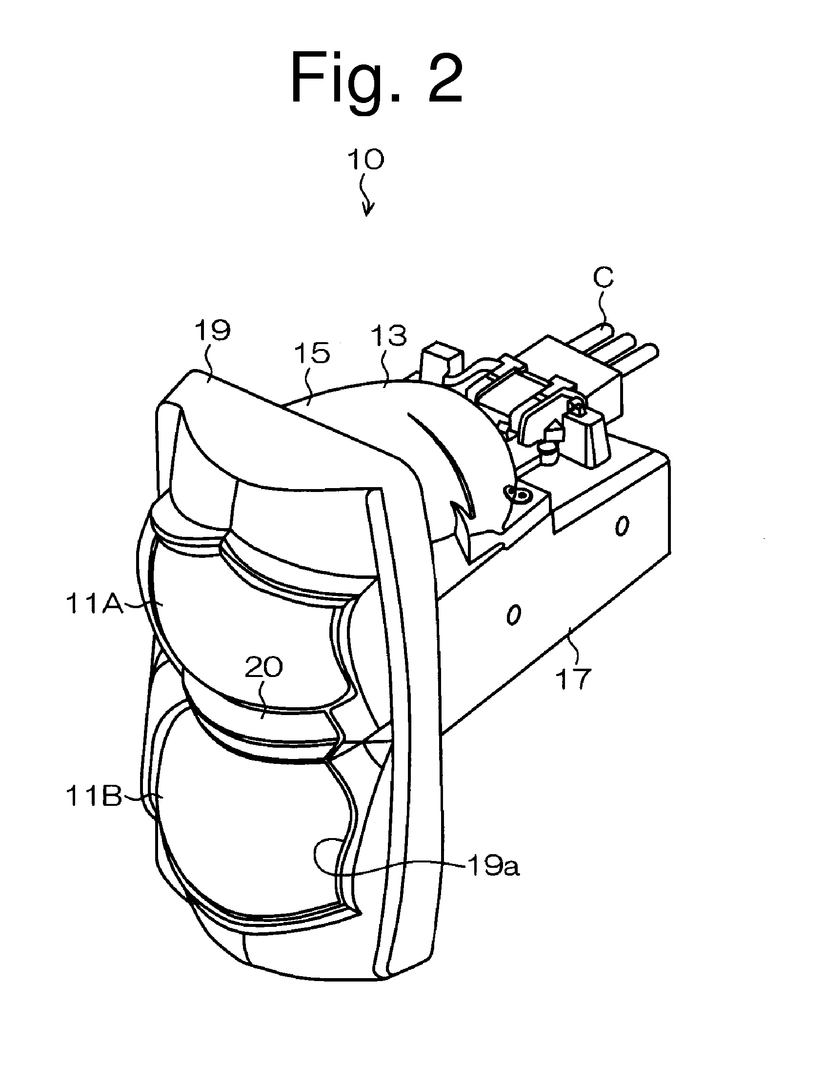
[0027]At least one vehicle lighting unit 10 of the present exemplary embodiment can be disposed on each of the front left and front right sides of a vehicle body, such as an automobile, and can be used as a vehicle headlight. Well-known aiming mechanisms (not shown) can be connected to the respective vehicle lighting units 10 so that their optical axes can be adjusted.

[0028]FIG. 2 is a perspective view of the vehicle lighting unit 10, and FIG. 3 is a front view thereof. FIG. 4 is a vertical cross-sectional view o...


PUM


Abstract

A vehicle lighting unit can be configured to allow the brightnesses of light observed through vertically arranged lenses to substantially match when the lenses are viewed from a certain viewpoint in front of the vehicle. The vehicle lighting unit can include: a first lens on a first upper optical axis; a second lens on a second lower optical axis; a semiconductor light-emitting device; a first revolved ellipsoidal reflector; a shade; a second revolved ellipsoidal reflector; and a third reflector. The third reflector is inclined at an inclination angle with respect to the horizontal plane adjusted such that light emitted from the semiconductor light-emitting device, reflected by the second reflector, focused at a second focal point of the second reflector, reflected by the third reflector, and passing through the second lens is directed in a direction at a predetermined upward angle with respect to the horizontal plane.

Description

[0001]This application claims the priority benefit under 35 U.S.C. §119 of Japanese Patent Application No. 2011-146159 filed on Jun. 30, 2011, which is hereby incorporated in its entirety by reference.TECHNICAL FIELD[0002]The presently disclosed subject matter relates to a vehicle lighting unit, and particularly to a vehicle lighting unit including vertically arranged lenses.BACKGROUND ART[0003]Vehicle lamps including vertically arranged lenses have been proposed (see, for example, Japanese Patent No. 4666160 or corresponding U.S. Pat. No. 7,325,954).[0004]As shown in FIG. 1, a vehicle lamp 200 described in Japanese Patent No. 4666160 can include vertically arranged lenses 210A and 210B, an HID bulb 220, an upper reflector 230A, a lower reflector 230B, and the like. In the vehicle lamp 200 configured as above, upward light emitted from the HID bulb 220 can be reflected by the upper reflector 230A, pass through the upper lens 210A, and then be projected toward the front. Downward lig...

Claims


Application Information

Patent Timeline
Patent Type & Authority Patents(United States)
IPC IPC(8): F21V13/12F21S8/10
CPCF21S48/1388F21S48/1159F21S41/147F21S41/255F21S41/321F21S41/333F21S41/43F21S41/338F21S41/365F21W2102/18F21V7/08F21V13/04
Inventor SEKIGUCHI, TATSUYASHIMADA
Owner STANLEY ELECTRIC CO LTD
Features
  • R&D
  • Intellectual Property
  • Life Sciences
  • Materials
  • Tech Scout
  • Unparalleled Data Quality
  • Higher Quality Content
  • 60% Fewer Hallucinations
Learn More