Fuel cell, and method of manufacturing a fuel cell
a technology of fuel cells and manufacturing methods, applied in the field of fuel cell sealing technology, can solve the problems of high cost, large size and the like of fuel cells, and achieve the effect of simplifying the manufacturing process of fuel cells
- Summary
- Abstract
- Description
- Claims
- Application Information
AI Technical Summary
Benefits of technology
Problems solved by technology
Method used
Image


Examples
first embodiment
A. First Embodiment
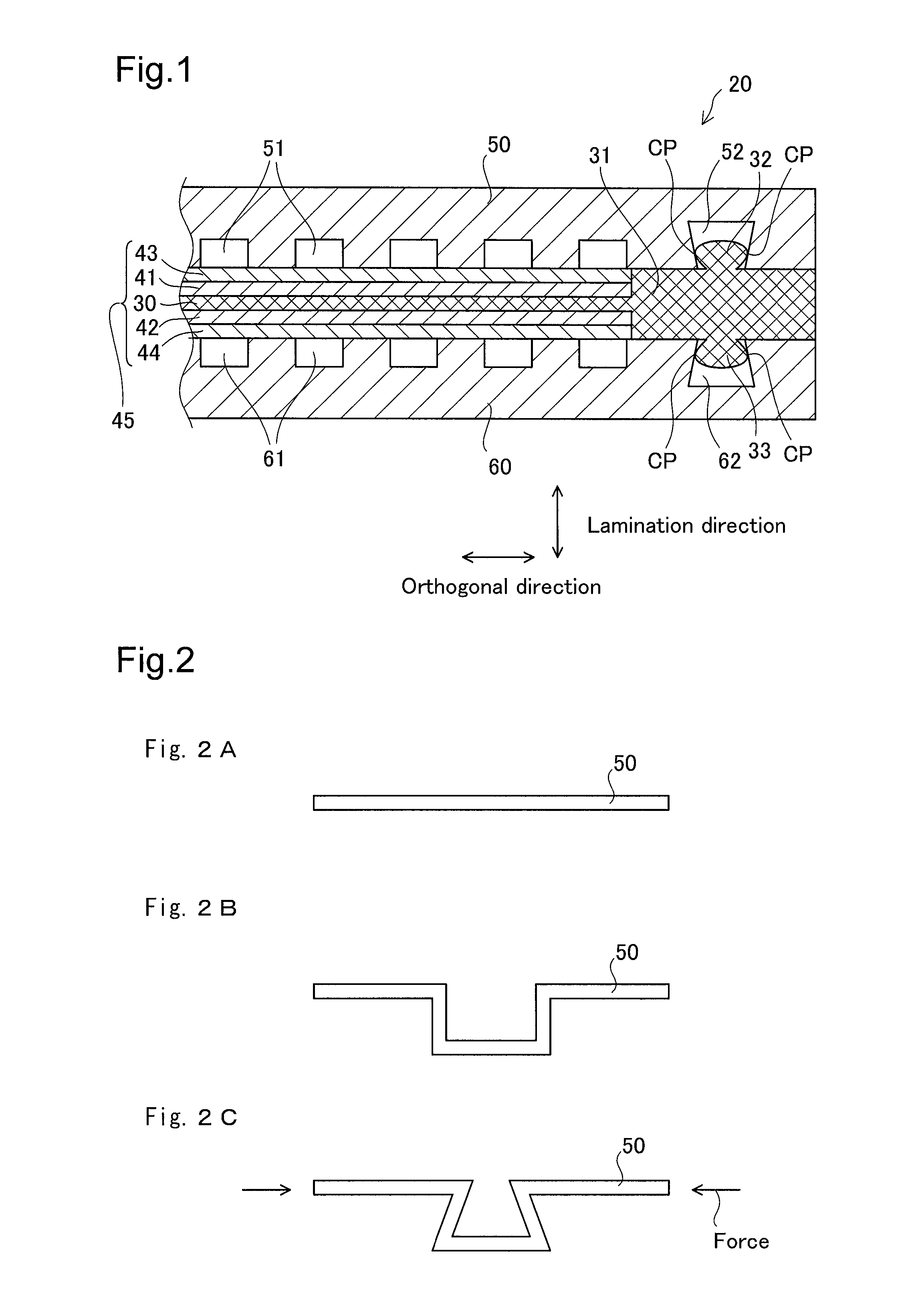
[0075]FIG. 1 is an explanatory drawing showing the schematic structure of a fuel cell 20 as a first embodiment of the present invention. FIG. 1 shows part of a cross section of the lamination direction of the members constituting the fuel cell 20. Following, this lamination direction is also simply called the lamination direction, and the direction orthogonal to the lamination direction is also called the orthogonal direction. Also, the surface orthogonal to the lamination direction of the members constituting the fuel cell 20 is also called the lamination surface. The fuel cell 20 is a solid polymer type fuel cell. The rated operating temperature of the fuel cell 20 of this embodiment is 70 to 90° C. As shown in the drawing, the fuel cell 20 is equipped with an electrolyte membrane 30, an anode electrode 41, a cathode electrode 42, gas diffusion layers 43 and 44, and separators 50 and 60, and is formed by these being laminated.
[0076]The electrolyte membrane 30 co...
second embodiment
B. Second Embodiment
[0099]A second embodiment of the present invention will be described. The second embodiment differs from the first embodiment only in the manufacturing method of the fuel cell. Here, the manufacturing method of the fuel cell of a second embodiment as the manufacturing method of the fuel cell 220 described above will be described. FIG. 6 is a process drawing showing the manufacturing method of the fuel cell 220. As shown in the drawing, with the manufacturing method of the fuel cell 220, first, the MEGA 245 and the separators 250 and 260 are prepared (step S310). At this point in time, the convex parts 232 and 233 are not formed on the electrolyte membrane 230 constituting the MEGA 245 prepared here.
[0100]When the MEGA 245 and the separators 250 and 260 are prepared, next, an ionomer 235 (liquid form electrolyte) is applied at the positions at which the convex parts 232 and 233 of the MEGA 245 are to be formed, said a different way, the positions corresponding to ...
third embodiment
C. Third Embodiment
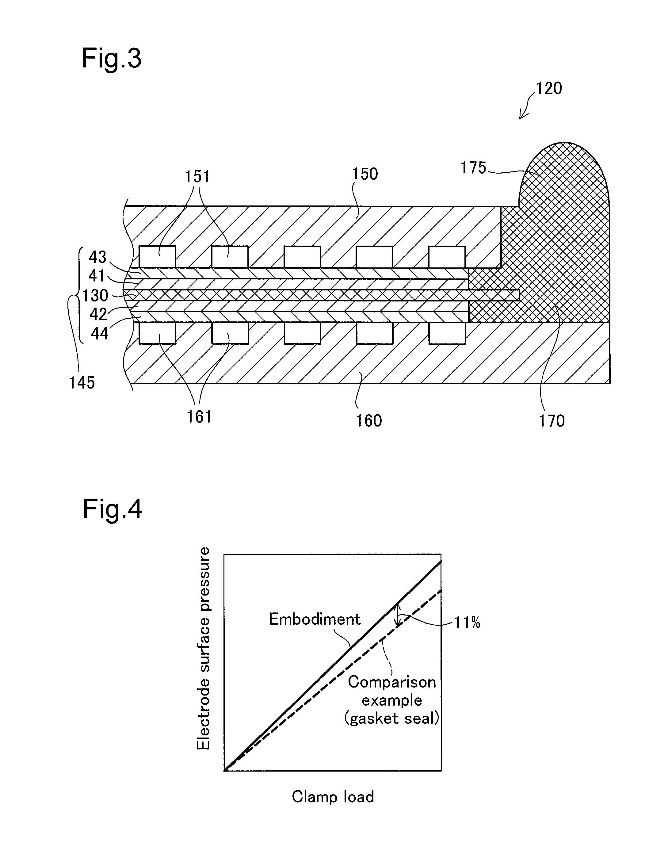
[0104]A third embodiment of the present invention will be described. FIG. 7 shows the schematic structure of a fuel cell 420 as a third embodiment. In FIG. 7, the same constitutional items as those of the first embodiment (FIG. 1) are given the same code numbers as in FIG. 2. Following, for the fuel cell 420, a description of the same constitutional items as those of the first embodiment will be omitted, and only the differences from the first embodiment will be described. The difference from the first embodiment is that the electrolyte membrane 430 of the MEGA 445 constituting the fuel cell 420 as the third embodiment is equipped with an internal member 471 on the inside of the outer edge part 431. This internal member 471 is a plate shaped member with a smaller elasticity than the electrolyte that forms the electrolyte membrane 430. With the cross section shown in FIG. 7, the internal member 471 is formed in a shape that roughly follows the convex shape of the c...
PUM
| Property | Measurement | Unit |
|---|---|---|
| operating temperature | aaaaa | aaaaa |
| thickness | aaaaa | aaaaa |
| area | aaaaa | aaaaa |
Abstract
Description
Claims
Application Information
 - R&D
- Intellectual Property
- Life Sciences
- Materials
- Tech Scout
- Unparalleled Data Quality
- Higher Quality Content
- 60% Fewer Hallucinations
Browse by: Latest US Patents, China's latest patents, Technical Efficacy Thesaurus, Application Domain, Technology Topic, Popular Technical Reports.
© 2025 PatSnap. All rights reserved.Legal|Privacy policy|Modern Slavery Act Transparency Statement|Sitemap|About US| Contact US: help@patsnap.com