Supercharge Your Innovation With Domain-Expert AI Agents!

Protective circuit for a rechargeable battery pack

a rechargeable battery pack and protection circuit technology, applied in secondary cell servicing/maintenance, cell components, instruments, etc., can solve the problems of restricting the performance of the entire rechargeable battery pack, affecting the overall performance of the cell row containing the weaker cell,

Active Publication Date: 2014-11-04
ANDREAS STIHL AG & CO KG
View PDF28 Cites 1 Cited by
  • Summary
  • Abstract
  • Description
  • Claims
  • Application Information

AI Technical Summary

Benefits of technology

[0005]It is an object of the invention to configure a protective circuit for an arrangement which includes a multiplicity of individual cells in a rechargeable battery pack in such a manner that, without complex monitoring, the failure of an individual cell in the entire cell arrangement can be identified rapidly and reliably.
[0009]By evaluating the potentials of the cell connectors of one cell row with the corresponding potentials of the cell connectors of the other cell row, it is therefore possible to generate a signal which can be utilized, for example, for switching off the rechargeable battery pack.
[0011]In a simple manner, the detected rechargeable battery pack and expediently factorized rechargeable battery pack potentials of the cell connectors situated at an identical location in the parallel cell row are directly compared with one another and a difference voltage is advantageously derived by subtraction, the magnitude of which difference voltage can be used directly for switching off the rechargeable battery pack. If the difference voltage exceeds a threshold value, a signal for switching off the rechargeable battery pack is output.

Problems solved by technology

A large cell network is only as good as its weakest cell; if one individual cell ages more rapidly than others, the cell row containing the weaker cell is impaired overall; in particular, compensation currents can flow within the rechargeable battery pack and restrict the performance of the entire rechargeable battery pack.

Method used


Image

  • Protective circuit for a rechargeable battery pack
  • Protective circuit for a rechargeable battery pack
  • Protective circuit for a rechargeable battery pack

Examples


Embodiment Construction

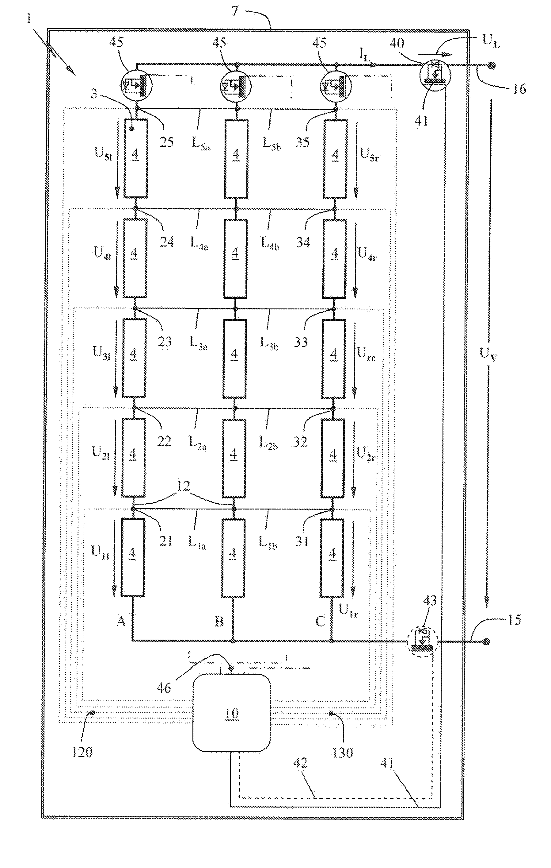
[0021]In the exemplary embodiment according to FIG. 1, a rechargeable battery pack 1 constructed from a multiplicity of cell blocks (2, 3) is shown. In the embodiment shown, an identical number of cell blocks 2 and 3 are connected in series to form respective cell rows A, B, C and D. The cell rows A, B, C and D are in parallel with one another and are connected by their ends to the terminal poles 15 and 16 of the rechargeable battery pack 1. The external supply voltage Uv is present between the terminal poles (15, 16).

[0022]In the embodiment, cell rows A, B, C and D each consist of ten cell blocks 2 or 3 connected in series one behind another. Here, in each case, five cell blocks (2, 3) form a structural unit 18. The structural units 18 of a cell row A, B, C and D are electrically connected to one another by a line segment, in particular a cable 13.

[0023]A cell block 3 is reproduced by way of example in FIG. 2. In the embodiment shown, the cell block 3 consists of three individual c...


PUM

PropertyMeasurementUnit
supply voltageaaaaaaaaaa
voltageaaaaaaaaaa

Abstract

A protective circuit for an arrangement includes a multiplicity of individual cells in a rechargeable battery pack. A predefined number of individual cells are connected in series in a cell row and at least two cell rows are mutually parallel, and at least one cell connector situated between the individual cells at a location of one cell row is electrically connected via a compensation line to the cell connector situated at an identical location of the parallel cell row, and the potential of the cell connector connected to the compensation line at one location of one cell row and the potential of the cell connector electrically connected to the compensation line at the same location of the parallel cell row are detected and the detected potentials are fed to an evaluation unit.

Description

CROSS REFERENCE TO RELATED APPLICATION[0001]This application claims priority of German patent application no. 10 2011 121 937.8, filed Dec. 22, 2011, the entire content of which is incorporated herein by reference.FIELD OF THE INVENTION[0002]The invention relates to a protective circuit for an arrangement comprising a multiplicity of individual cells in a rechargeable battery pack, wherein a predefined number of individual cells are connected in series in a cell row.BACKGROUND OF THE INVENTION[0003]Such rechargeable battery pack arrangements comprising, for example, cells based chemically on lithium are used in handheld work apparatus and are intended to ensure, in conjunction with high performance, a long service life of the apparatus supplied with power via the rechargeable battery pack.[0004]A large cell network is only as good as its weakest cell; if one individual cell ages more rapidly than others, the cell row containing the weaker cell is impaired overall; in particular, com...

Claims


Application Information

Patent Timeline
Patent Type & Authority Patents(United States)
IPC IPC(8): H01M10/44H01M10/48H01M10/052H02H7/18H02H3/00G01R31/36H01M2/10H02H3/20H01M50/204
CPCH02H3/20G01R31/3658H01M10/482H01M2/1022G01R31/362H02J7/00H01M10/441H02H7/18H01M10/052Y02E60/12G01R31/3835G01R31/396Y02E60/10H01M50/204
Inventor LIEBHARD, GERNOTGAUL, HENRIK
Owner ANDREAS STIHL AG & CO KG
Features
  • R&D
  • Intellectual Property
  • Life Sciences
  • Materials
  • Tech Scout
  • Unparalleled Data Quality
  • Higher Quality Content
  • 60% Fewer Hallucinations
Learn More