Supercharge Your Innovation With Domain-Expert AI Agents!

Apparatus and method for controlling fluid flow from a formation

a technology of fluid flow and apparatus, which is applied in the direction of fluid removal, wellbore/well accessories, sealing/packing, etc., can solve the problems of inconvenient operation, inconvenient maintenance, and inability to adjust the pre-set passive flow control device for the downhol

Active Publication Date: 2014-12-16
BAKER HUGHES HLDG LLC
View PDF56 Cites 47 Cited by
  • Summary
  • Abstract
  • Description
  • Claims
  • Application Information

AI Technical Summary

Problems solved by technology

Therefore, oil between the formation and the wellbore may not flow evenly through the various inflow control devices.
Such pre-set passive flow control devices are not configured for downhole adjustments to alter a flow rate.
Such methods are very expensive and time consuming.

Method used


Image

  • Apparatus and method for controlling fluid flow from a formation
  • Apparatus and method for controlling fluid flow from a formation
  • Apparatus and method for controlling fluid flow from a formation

Examples


Embodiment Construction

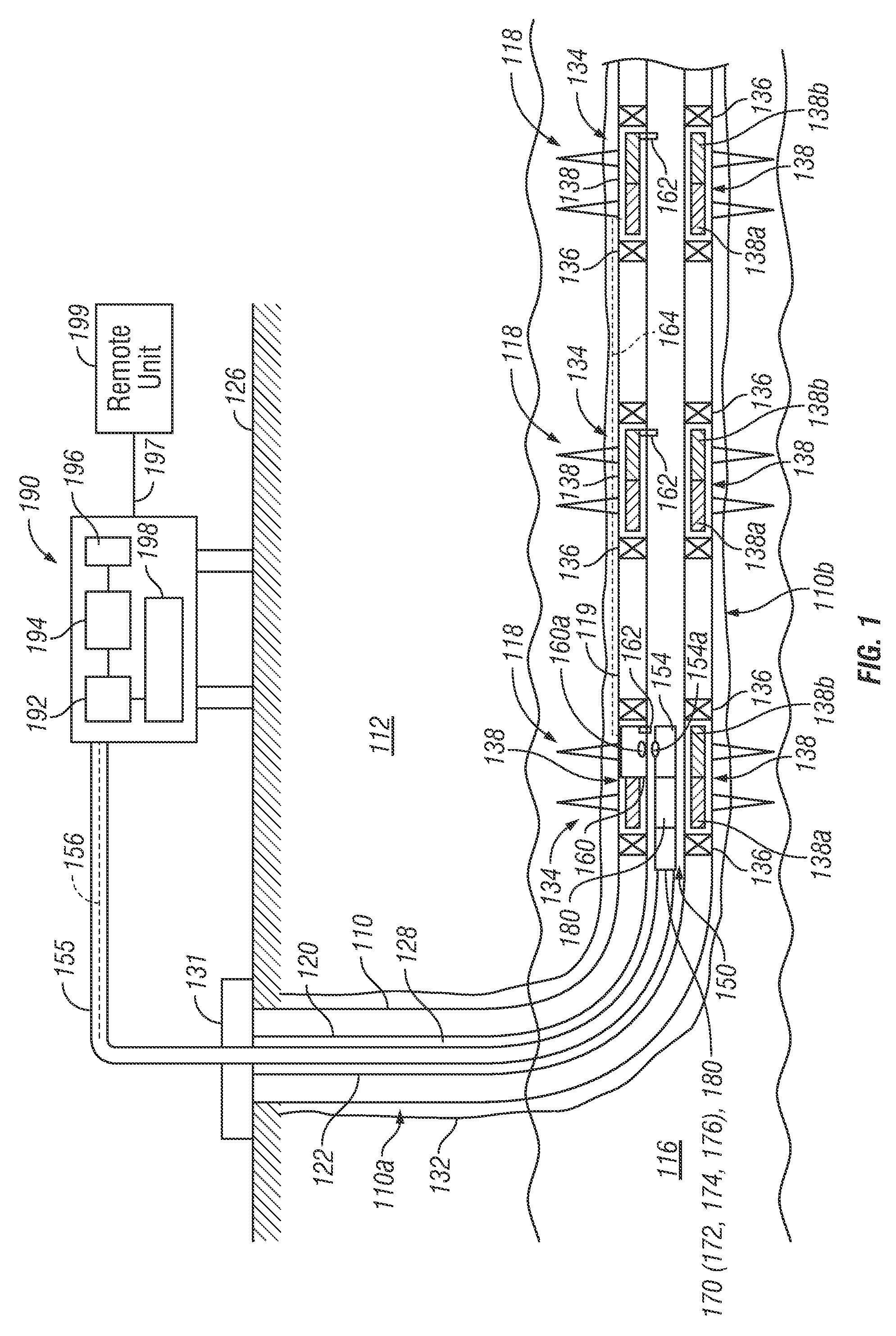
[0012]The present disclosure relates to apparatus and methods for controlling flow of fluids in a well. The present disclosure provides certain exemplary drawings to describe certain embodiments of the apparatus and methods that are to be considered exemplification of the principles described herein and are not intended to limit the concepts and disclosure to the illustrated and described embodiments.

[0013]FIG. 1 is a schematic diagram of an exemplary production wellbore system 100 that includes a wellbore 110 drilled through an earth formation 112 and into a production zone or reservoir 116. The wellbore 110 is shown lined with a casing 132 having a number of perforations 118 that penetrate and extend into the production zone 116 so that production fluids may flow from the production zone 116 into the wellbore 110. The exemplary wellbore 110 is shown to include a vertical section 110a and a substantially horizontal section 110b. The wellbore 110 includes a production string (or pro...


PUM


Abstract

In one aspect, an apparatus for controlling fluid flow between a formation and a tubular is provided, wherein the apparatus includes a retrievable communication device configured to be conveyed to a selected location in the tubular downhole. The apparatus also includes a control node configured to communicate with the retrievable communication device at the selected location, a flow control device coupled to and controlled by the control node and a sensor coupled to the control node, wherein the sensor and flow control device are downhole of the control node.

Description

BACKGROUND OF THE DISCLOSURE[0001]1. Field of the Disclosure[0002]The disclosure relates generally to an apparatus and method for control of fluid flow between subterranean formations and a production string in a wellbore.[0003]2. Description of the Related Art[0004]To form a wellbore or borehole in a formation, a drilling assembly (also referred to as the “bottom hole assembly” or the “BHA”) carrying a drill bit at its bottom end is conveyed downhole. The wellbore may be used to store fluids in the formation or obtain fluids from the formation, such as hydrocarbons. In some cases the wellbore is completed by placing a casing along the wellbore length and perforating the casing adjacent each production zone (hydrocarbon bearing zone) to extract fluids (such as oil and gas) from the associated a production zone. In other cases, the wellbore may be open hole, i.e. no casing. One or more inflow control devices are placed in the wellbore to control the flow of fluids into the wellbore. ...

Claims


Application Information

Patent Timeline
Patent Type & Authority Patents(United States)
IPC IPC(8): E21B33/12E21B43/12E21B34/14
CPCE21B43/12
Inventor NEWTON, DANIELO'MALLEY, EDWARD J.
Owner BAKER HUGHES HLDG LLC
Features
  • R&D
  • Intellectual Property
  • Life Sciences
  • Materials
  • Tech Scout
  • Unparalleled Data Quality
  • Higher Quality Content
  • 60% Fewer Hallucinations
Learn More