Supercharge Your Innovation With Domain-Expert AI Agents!

Solid state lighting device

a lighting device and solid state technology, applied in the direction of lighting support devices, fixed installations, lighting and heating apparatus, etc., can solve the problems of low efficiency, high cost of ownership, and greatly reduced life span, and achieve the effect of high efficiency

Inactive Publication Date: 2015-01-06
THRAILKILL JOHN E +1
View PDF8 Cites 2 Cited by
  • Summary
  • Abstract
  • Description
  • Claims
  • Application Information

AI Technical Summary

Benefits of technology

[0008]It is, therefore, an object of the present invention to provide a high efficiency LED lighting device or source which emulates the lighting characteristics of an incandescent light source.

Problems solved by technology

Incandescent lighting remains popular despite the high cost of ownership due to low efficiency and short product life span, especially when the lighting is cycled on and off frequently.
As with incandescent sources, however, life span is greatly reduced when the bulbs are frequently cycled on and off.
Fluorescent lighting also suffers from what is generally considered an unnatural quality of light output.
Also, dimming a fluorescent product is problematic in that only certain types can be dimmed and then only over a narrow output range.
Further, fluorescent products are not capable of spectrally “warming up” at lower power input levels and may even “cool down”, creating an even more unnatural effect.
In addition, toxic materials, e.g. mercury, employed in the manufacture of the fluorescent devices require a special disposal process that is often ignored, leading to environmental damage.
The high degree of secondary diffusion required to create “soft”, diffuse lighting effects can greatly reduce the overall efficiency of an LED lighting fixture.
While this is beneficial for a number of technical applications, the LEDs cannot be dimmed to produce the warmer light output that many consumers prefer for general lighting.
Lastly, LEDs can only dissipate waste heat through the process of thermal conduction.
Unfortunately, most lighting fixtures have been designed for incandescent light sources where radiation is the primary mode of waste heat dissipation.

Method used


Image

  • Solid state lighting device
  • Solid state lighting device
  • Solid state lighting device

Examples


Embodiment Construction

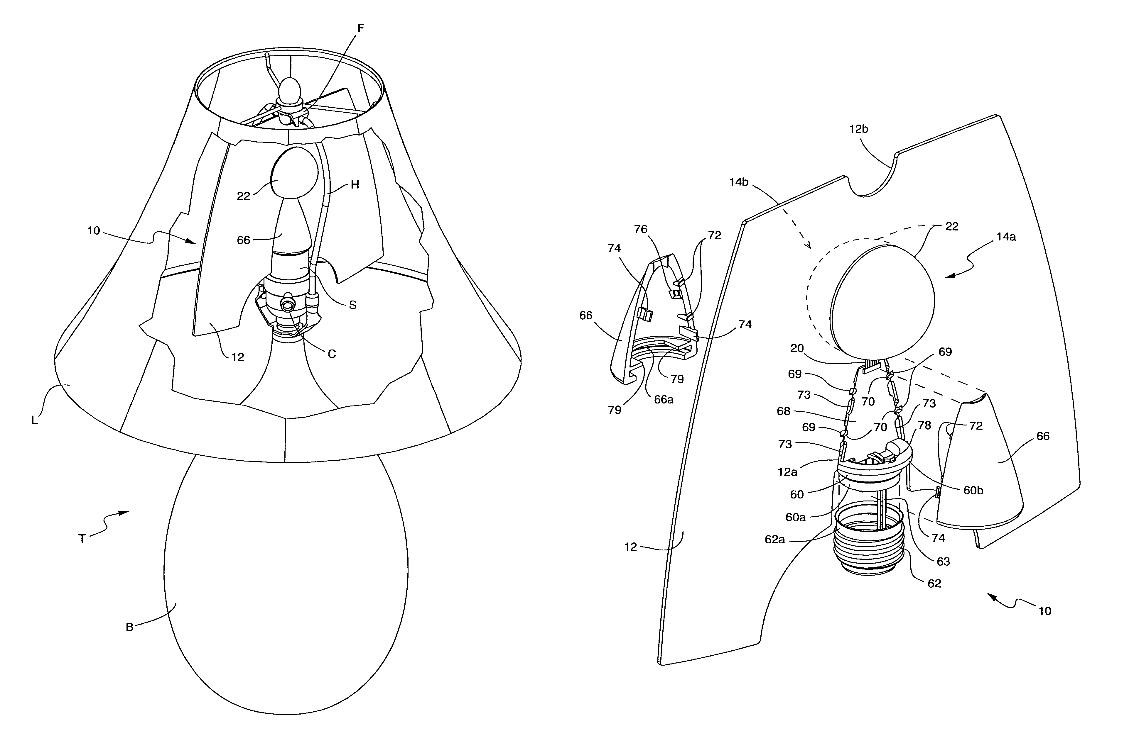
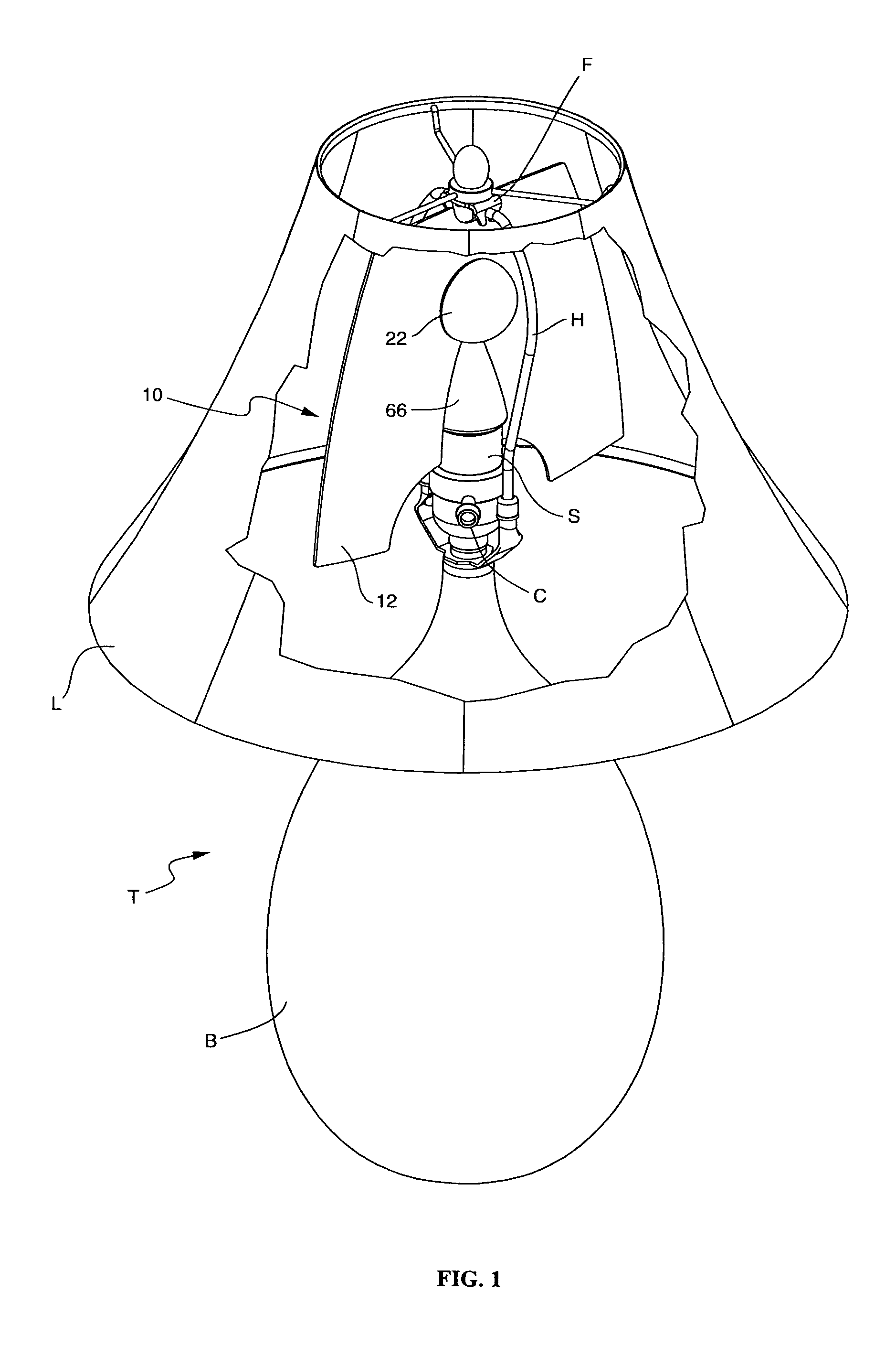
[0035]Refer now to FIG. 1 of the drawings which shows generally at 10 a two-sided solid state lighting device or source according to the invention incorporated into a table lamp T. Lamp T has a base B which may support a conventional switchable socket S whose switching control C extends from the side of the socket. A conventional harp H is mounted to the top of base B just below the socket and extends up and around device 10 so that it can support a lampshade L. For convenience, we will refer to device 10 in this lamp context as a “bulb” because it can be turned on and off like a regular incandescent bulb by operating the switch control C. Also, by separating harp H with shade L from socket S in the usual way, the bulb 10 can be screwed into socket S like a conventional incandescent bulb.

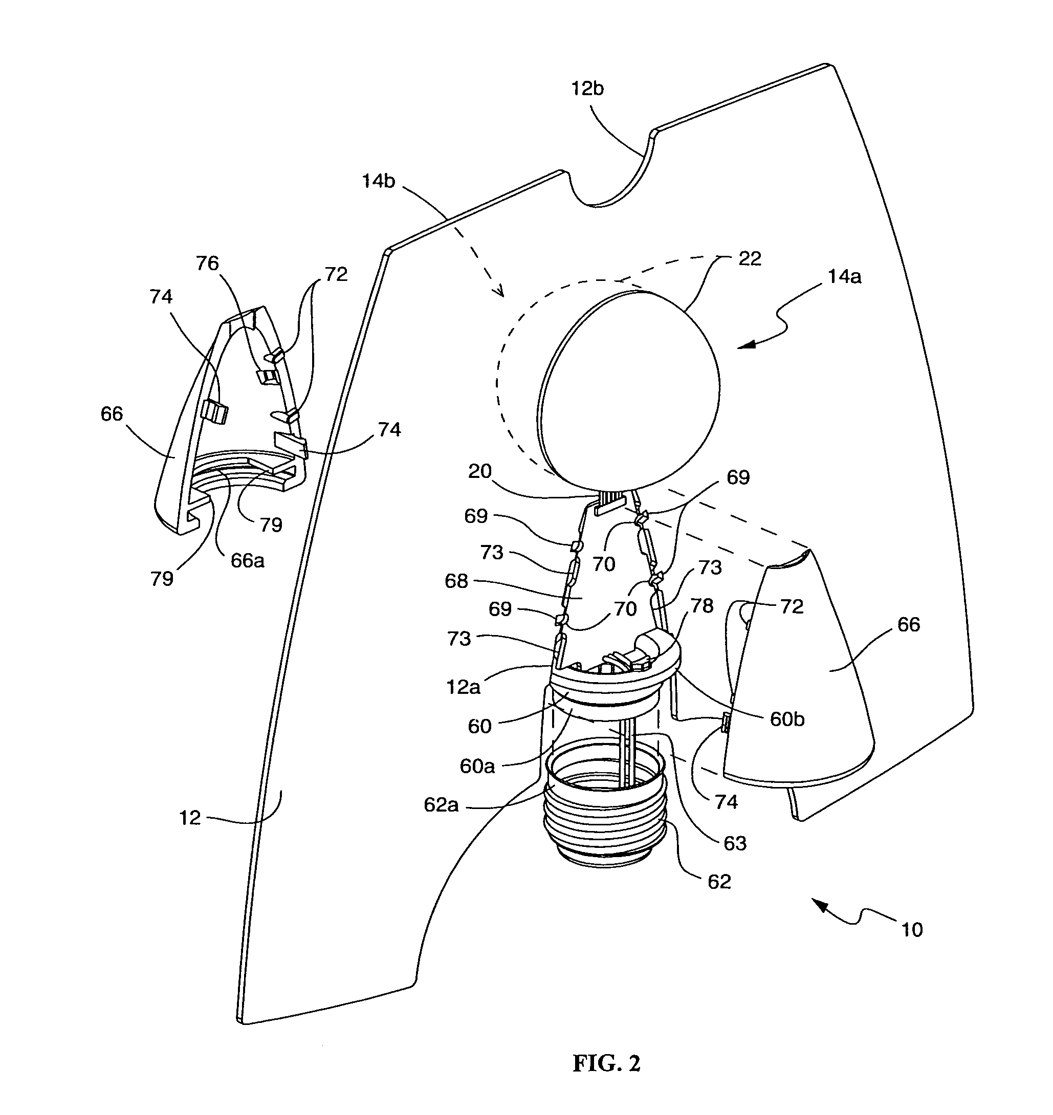
[0036]Referring now to FIGS. 1 to 3, in this embodiment, the bulb 10 is a component system comprising a thermal dissipator in the form of a flat, thermally conductive and preferably reflective plate...


PUM


Abstract

A solid state lighting device includes a relatively rigid, thermal dissipation plate with opposite sides, a printed circuit in intimate thermal contact with one side of the plate, at least one LED positioned against and electrically connected to the printed circuit and a shell having a rim secured to the one side of the plate so that the shell substantially covers the LED whereby when the LED is energized, light therefrom radiates into the shell and heat from the LED is conducted away by the plate.

Description

CROSS-REFERENCE TO RELATED APPLICATION[0001]This application is a continuation-in-part of Ser. No. 12 / 785,602, filed May 24, 2010, the contents of which is hereby incorporated by reference herein.BACKGROUND OF THE INVENTION[0002]The present invention relates generally to a solid state lighting device or source of the general purpose type. In particular, the invention relates to such a device which comprises a component system incorporating light emitting diodes (LEDs) in order to simulate general purpose incandescent lighting devices.[0003]The present invention further concerns lighting fixtures that incorporate the aforementioned component system in either a single sided or double sided (opposed) configuration.[0004]General purpose LED lighting devices are used primarily in residential and commercial office settings. LED light sources, as well as compact fluorescent (CFL) and linear fluorescent light sources, are generally recognized as the likely replacements for incandescent ligh...

Claims


Application Information

Patent Timeline
Patent Type & Authority Patents(United States)
IPC IPC(8): F21V5/04F21K99/00F21S8/00F21S8/06F21V3/00F21V3/02F21V13/04F21V17/00F21V17/16F21V29/00F21Y101/02
CPCF21V29/004F21V29/2212F21K9/00F21K9/135F21S8/033F21S8/06F21S8/063F21V3/02F21V7/20F21Y2101/02F21V29/2293F21V3/00F21V13/04F21V17/005F21V17/164F21V29/505F21V29/508F21V29/70F21V29/83F21K9/232F21Y2115/10
Inventor THRAILKILL, JOHN E.
Owner THRAILKILL JOHN E
Features
  • R&D
  • Intellectual Property
  • Life Sciences
  • Materials
  • Tech Scout
  • Unparalleled Data Quality
  • Higher Quality Content
  • 60% Fewer Hallucinations
Learn More