Supercharge Your Innovation With Domain-Expert AI Agents!

Sheet feed rolling element for use in an electrophotographic device and mold for injection molding for producing the sheet feed rolling element

a technology of electrophotography and rolling element, which is applied in the direction of manufacturing tools, portable power tools, transportation, etc., can solve the problems of time-consuming and troublesome post-treatment, difficult to prevent pl marks, etc., and achieves high image quality.

Active Publication Date: 2015-01-13
NTN CORP
View PDF22 Cites 0 Cited by
  • Summary
  • Abstract
  • Description
  • Claims
  • Application Information

AI Technical Summary

Benefits of technology

The solution prevents the formation of circumferential bulges on the sheet sliding contact surface, eliminating the need for post-treatments and ensuring high image quality without streaks on transfer sheets.

Problems solved by technology

Such post-treatment is time-consuming and troublesome.
But it may be difficult to prevent the PL mark from protruding from the sheet sliding contact surface using the surface sink mark, because the sheet sliding contact surface of the sheet feed rolling element has a small outer diameter.
With a sheet feed rolling element having a film-like sheet sliding contact surface too, it is difficult to prevent the PL mark from protruding from the sheet sliding contact surface using the surface sink mark, because the outer peripheral portion has a small wall thickness.
Such post-working is troublesome.
Similar problems are observed in a sheet feed rolling element formed using the mold for injection molding as disclosed in Patent document 4, and having a film-like portion having the sheet sliding contact surface and a roller portion having shoulders on both sides which are formed by curved chamfers.

Method used


Image

  • Sheet feed rolling element for use in an electrophotographic device and mold for injection molding for producing the sheet feed rolling element
  • Sheet feed rolling element for use in an electrophotographic device and mold for injection molding for producing the sheet feed rolling element
  • Sheet feed rolling element for use in an electrophotographic device and mold for injection molding for producing the sheet feed rolling element

Examples


example 1

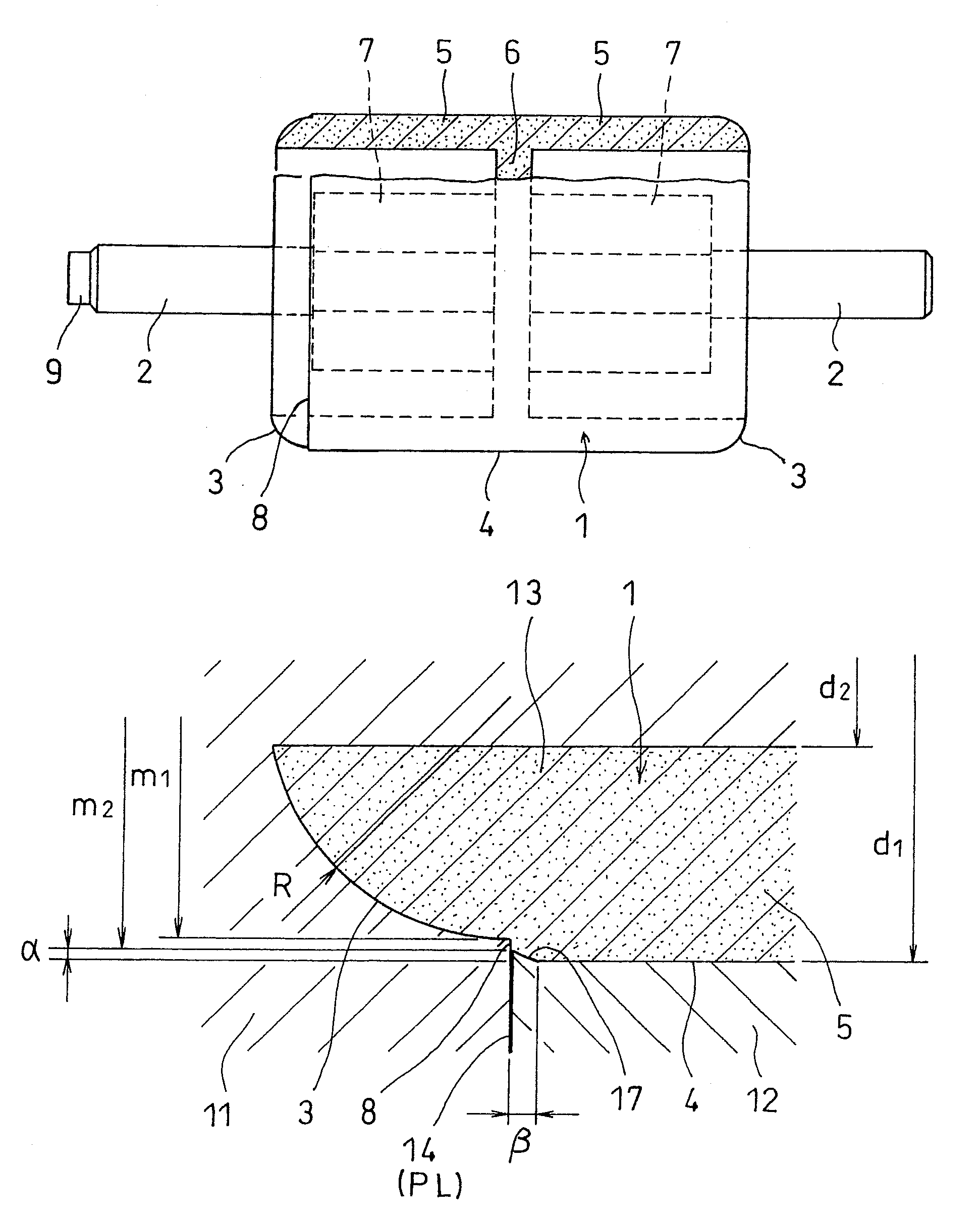
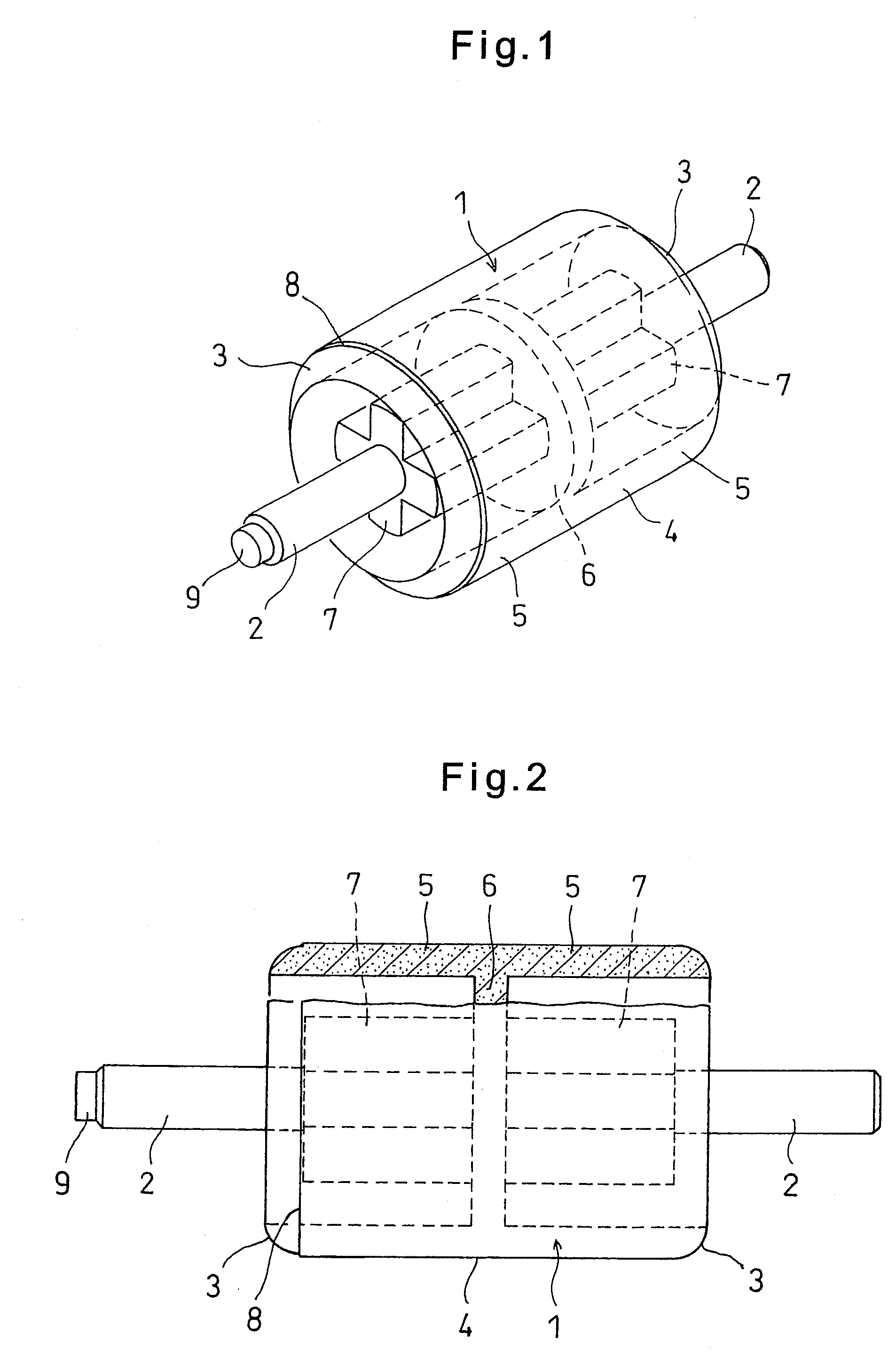
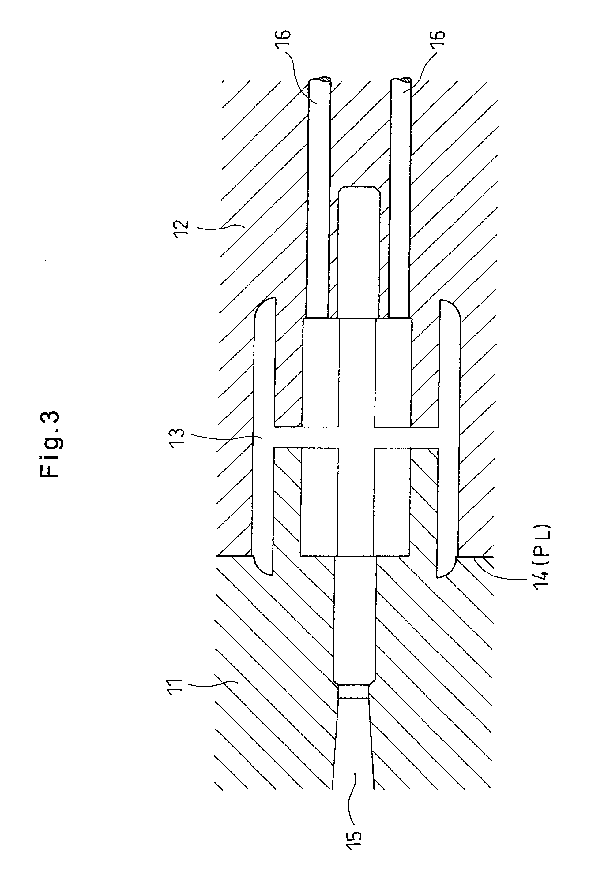
[0046]Using the mold for injection molding shown in FIGS. 3 to 5, a sheet discharge roller as shown in FIGS. 1 and 2 was formed by the injection molding of ETFE. The sheet discharge roller thus formed had a diameter of 10.0 mm, an inner diameter of 8.0 mm and an axial length of 12.0 mm at its roller portion 1, and the curved chamfer of each shoulder 3 had a radius R of 1 mm. The outer peripheral surface 4 was a cylindrical surface parallel to the axis. The difference in radius between the opening diameters m2 and m1 of the cavity 13 at PL 14 was 0.1 mm; the depth α of the chamfer was 0.05 mm; and the width β of the chamfer was 0.1 mm. When the portion of the sheet discharge roller formed where there is PL 14 was observed under a toolmakers microscope, no bulge was found on the outer peripheral surface 4.

[0047]As a comparative example, using a mold for injection molding shown in FIG. 9, which has a diameter of 12.5 mm, an inner diameter of 10.0 mm and an axial length of 11.5 mm at th...


PUM

PropertyMeasurementUnit
radiusaaaaaaaaaa
distanceaaaaaaaaaa
thicknessaaaaaaaaaa

Abstract

A sheet feed rolling element for an electrophotographic device includes a roller portion and shoulders on both sides formed by curved chamfers. A parting line between the fixed mold plate and the movable mold plate of an injection mold is located at the boundary between one shoulder and the roller portion outer periphery, a step is provided at the boundary due to a difference between the opening diameter of the cavity portion defined by the fixed mold plate and the opening diameter of the cavity portion defined by the movable mold plate so the one shoulder has a smaller diameter than the outer peripheral surface, and a chamfer is provided adjacent to the one shoulder to absorb any difference in molding shrinkage rate due to a difference in molecular orientation of resin at the step, thereby preventing circumferential bulging on the outer periphery of the formed roller portion.

Description

TECHNICAL FIELD[0001]This invention relates to a sheet feed rolling element for feeding sheet on which images are formed in electrophotographic devices such as copiers, facsimiles and laser printers, and a mold for forming such a roller by injection molding.BACKGROUND ART[0002]In an electrophotographic device which utilizes an electrophotographic process, such as a copier or a laser printer, images formed on a photosensitive material by an electrophotographic process are transferred onto transfer sheets in the form of toner images. After fixing the transferred images on the sheets with an image fixing unit, the sheets are discharged from the device. The image fixing unit comprises an image fixing roller with a built-in heater, and a pressure roller pressed against the image fixing roller. Transfer sheets carrying toner images are passed through a nip portion between the rollers to melt and fix toner to the transfer sheets by heating and pressing. Then, the transfer sheets are discha...

Claims


Application Information

Patent Timeline
Patent Type & Authority Patents(United States)
IPC IPC(8): F16C13/00B29C45/00B29L31/32B65H27/00
CPCB29C45/0025B65H27/00B29C2045/0034B29L2031/322B65H2401/113B65H2402/80B65H2404/135B65H2801/06B65H2401/11
Inventor ABE, HIROHISAMUNEDA, NORIKAZU
Owner NTN CORP
Features
  • R&D
  • Intellectual Property
  • Life Sciences
  • Materials
  • Tech Scout
  • Unparalleled Data Quality
  • Higher Quality Content
  • 60% Fewer Hallucinations
Learn More