Supercharge Your Innovation With Domain-Expert AI Agents!

Brushless motor

a brushless, electric motor technology, applied in the direction of machines/engines, magnetic circuit rotating parts, magnetic circuit shape/form/construction, etc., can solve the problems of large cogging torque, great vibration and nois

Active Publication Date: 2015-01-13
JOHNSON ELECTRIC SA
View PDF14 Cites 7 Cited by
  • Summary
  • Abstract
  • Description
  • Claims
  • Application Information

AI Technical Summary

Benefits of technology

The present invention provides a brushless motor that has a stator with teeth and windings, and a rotor with a shaft, magnetic poles, and grooves. The angle between the stator and rotor is 15-30 degrees. The grooves are evenly spaced and run along the surface of the rotor. The number of magnetic poles is 4 and the number of teeth is 6, with the boundary lines between magnetic poles being skewed by an angle a relative to the shaft. The start charging points of the magnetic poles are offset from the ends of the corresponding grooves. The bladeless fan has a base with an inner chamber and a ring nozzle, and the motor is positioned within the chamber. The fan also has an impeller to move air from outside the base into the chamber, through the inner passage, out the ring outlet, and over the Coanda surface.

Problems solved by technology

Traditional brushless motors used in industry have a wide opening to the slot between the teeth of the stator and a small air-gap between the rotor and the stator, which results in a large cogging torque and therefore great vibration and noise.

Method used


Image

  • Brushless motor
  • Brushless motor
  • Brushless motor

Examples


Embodiment Construction

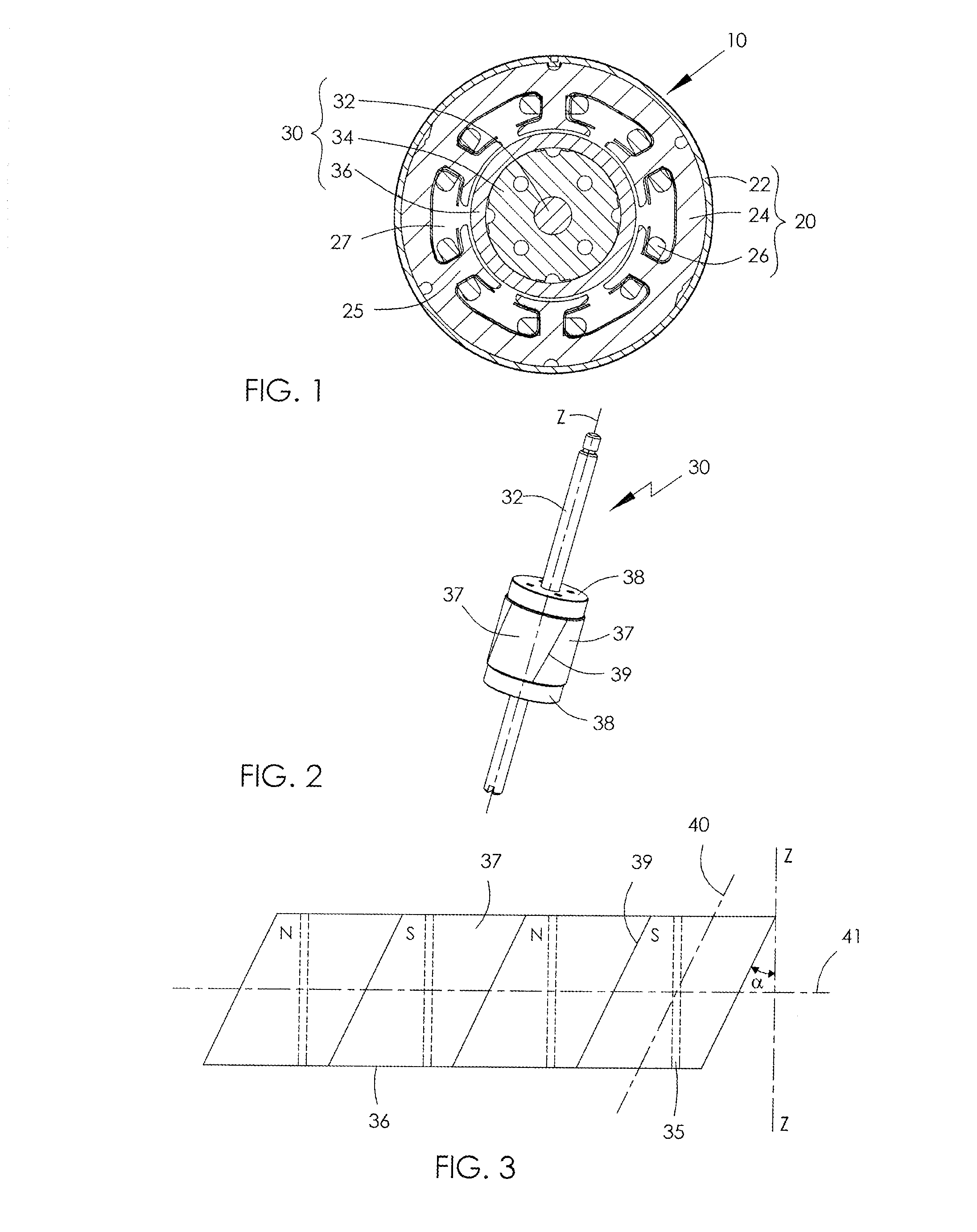
[0027]FIG. 1 illustrates a brushless motor according to a preferred embodiment of the present invention. The motor 10 comprises a stator 20 and a rotor 30 rotatably installed inside the stator 20. The stator 20 comprises a housing 22, a stator core 24 installed at the inner surface of the housing 22, and a plurality of coils 26 wound on the stator core 24. The stator core 24 comprises a plurality of spaced teeth 25 extending inwardly there from. Slots 27 are formed between adjacent teeth 25 for receiving the coils 26. A cylindrical space is formed between the inner ends of the teeth 25.

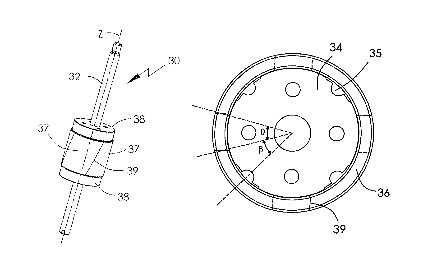
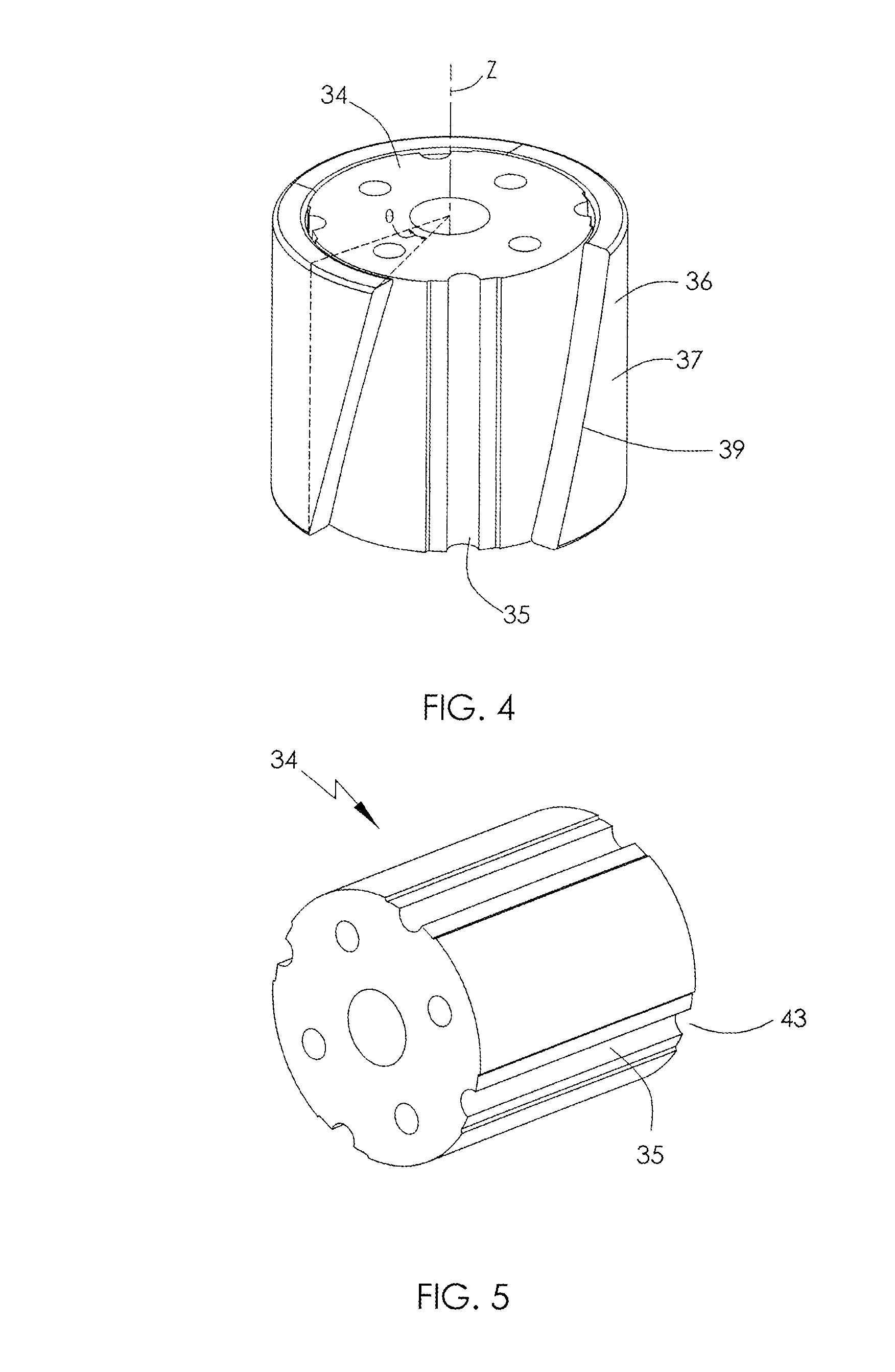
[0028]The rotor 30 comprises a shaft 32 rotatably supported by the stator 20, a rotor core 34 fixed on the shaft 32, a ring magnet 36 fixed on the outer circumferential surface of the rotor core 34, and a pair of balancing members 38 fixed at opposite ends of the rotor core 34. The rotor core 34 and magnet 36 are received in the cylindrical space formed by the teeth of the stator 20 and the magnet 36 ...


PUM


Abstract

A brushless motor has a stator and a rotor rotatably installed inside of the stator. The stator includes a stator core with teeth protruding inwardly and windings wound on the teeth. The rotor includes a shaft, a rotor core fixed on the shaft, and a ring magnet fixed to the circumferential outer surface of the rotor core. The magnet includes a plurality of magnetic poles radially magnetized so that north poles and south poles are arranged alternately in the circumferential direction. Boundary lines between magnetic poles are skewed by an angle relative to an axis of the shaft.

Description

CROSS REFERENCE TO RELATED APPLICATIONS[0001]This non-provisional patent application claims priority under 35 U.S.C. §119(a) from Patent Application No. 201020502993.X filed in The People's Republic of China on Aug. 20, 2010 and Patent Application No. 201020573398.5 filed in The People's Republic of China on Oct. 21, 2010.FIELD OF THE INVENTION[0002]This invention relates to electric motors, and in particular to a brushless electric motor.BACKGROUND OF THE INVENTION[0003]A brushless motor comprises a stator and a rotor rotatably mounted to the stator. The stator comprises a stator core comprising inwardly extending teeth and windings wound about the teeth. The rotor comprises a shaft rotatably supported by the stator, a rotor core fixed to the shaft and magnets fixed to the rotor core.[0004]Traditional brushless motors used in industry have a wide opening to the slot between the teeth of the stator and a small air-gap between the rotor and the stator, which results in a large coggin...

Claims


Application Information

Patent Timeline
Patent Type & Authority Patents(United States)
IPC IPC(8): H02K1/27
CPCH02K1/278F04F5/16F04F5/46H02K2201/06Y10T137/2224
Inventor JIANG, MAO XIONGLI, YUEZHANG, TAOXIAO, SAN RUANCHAN, LIK HON
Owner JOHNSON ELECTRIC SA
Features
  • R&D
  • Intellectual Property
  • Life Sciences
  • Materials
  • Tech Scout
  • Unparalleled Data Quality
  • Higher Quality Content
  • 60% Fewer Hallucinations
Learn More