Supercharge Your Innovation With Domain-Expert AI Agents!

Fixing pressure member and production method therefor

a technology of fixing pressure and production method, which is applied in the direction of ohmic-resistance heating, electrographic process, instruments, etc., can solve the problems of increasing the friction resistance of sheet-like members, reducing the service life of fixing devices, and requiring a large amount of time and cost for processing and attachment, etc., to achieve excellent durability, reduce the number of processing and assembly steps, and reduce the cost

Inactive Publication Date: 2015-02-17
NOK CORP +1
View PDF12 Cites 7 Cited by
  • Summary
  • Abstract
  • Description
  • Claims
  • Application Information

AI Technical Summary

Benefits of technology

The solution results in a fixing pressure member with improved durability and reduced production costs, preventing displacement and deformation under high pressure, ensuring reliable long-term operation.

Problems solved by technology

Therefore, the sheet-like member poses a problem in that its processing and attachment require a large amount of time and cost.
In addition, problems arise in that the sheet-like member, which covers the pressure pad and is partially fixed thereto, deforms in a movement direction through repeated sliding, and the friction resistance of the sheet-like member increases through continued use thereof.
In the worst case, the sheet-like member may cause stoppage of the rotation of the fixing belt, or may cause shortening of the service life of the fixing device.

Method used


Image

  • Fixing pressure member and production method therefor
  • Fixing pressure member and production method therefor
  • Fixing pressure member and production method therefor

Examples


example 1

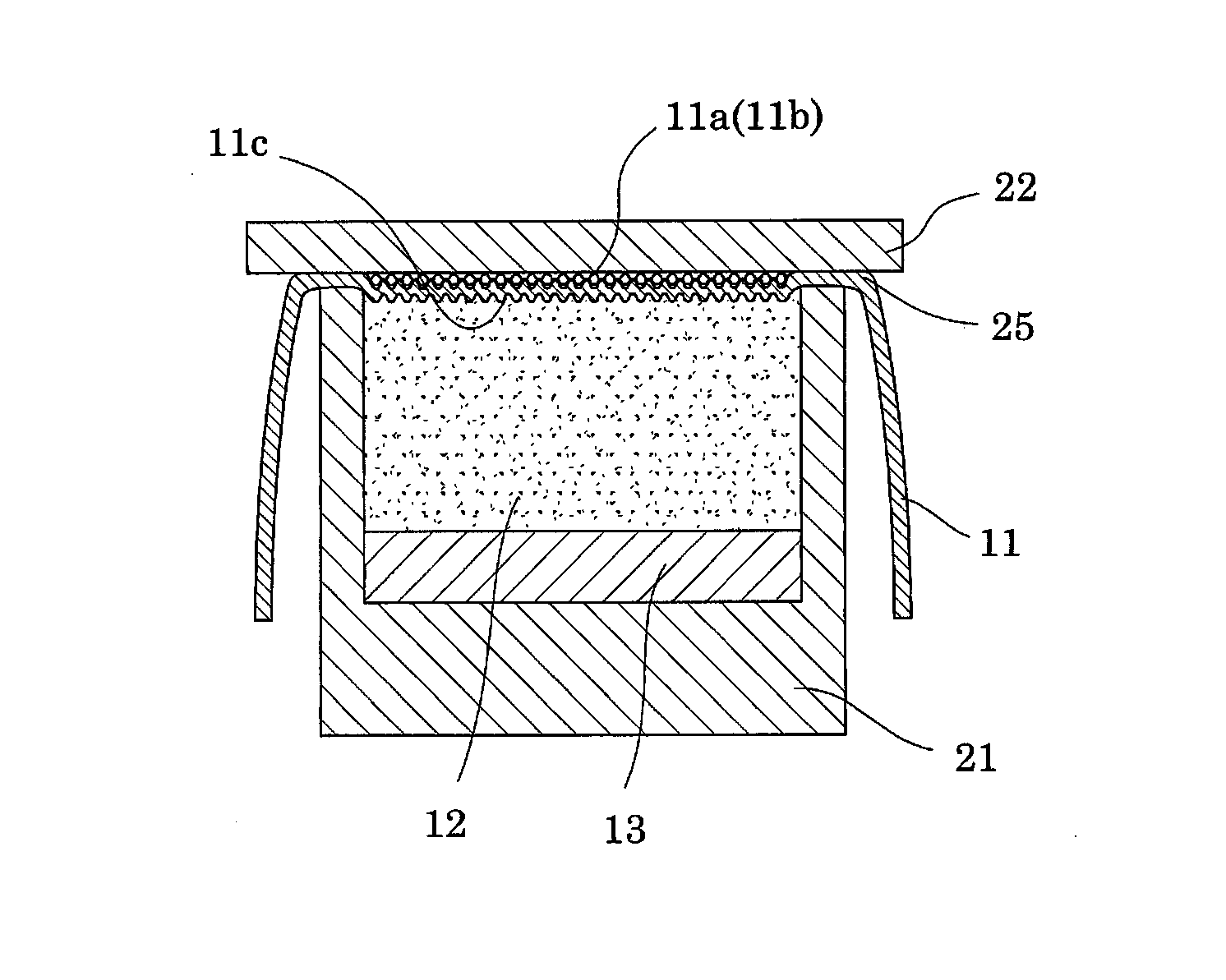
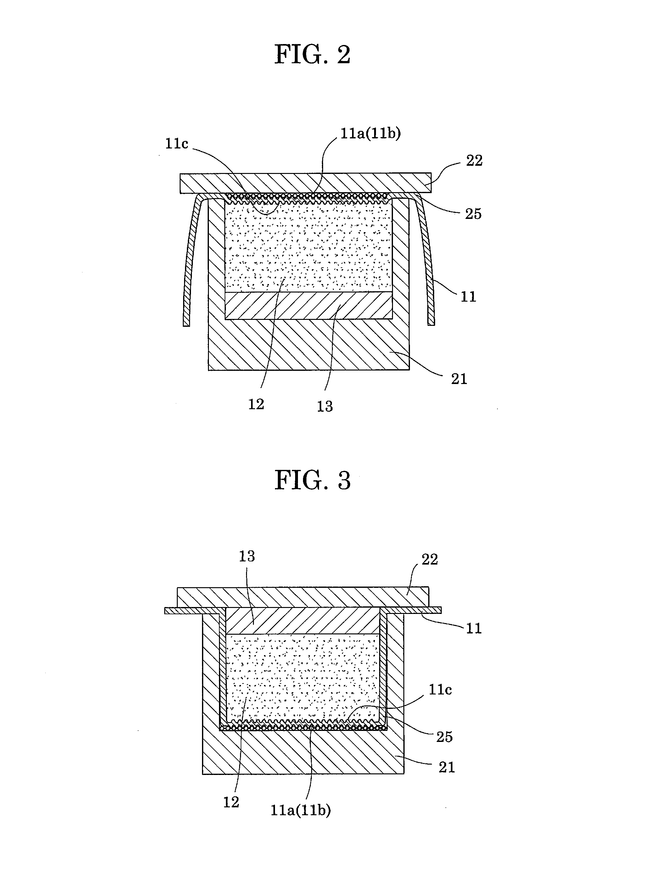
[0027]As shown in FIG. 2, dies having a size corresponding to that of a fixing pressure member were provided. An SUS plate (thickness: 2 mm), serving as a support 13, was provided, and a silicone rubber primer was applied to the SUS plate. The SUS plate was placed in a lower die 21, and liquid silicone rubber (DY35-363, product of Dow Corning Tray, Co., Ltd.) was added to the lower die. Separately, a PFA film (thickness: 70 μm), serving as a sliding sheet 11, was provided. One surface of the PFA film was subjected to etching treatment with liquid ammonia, and a silicone rubber primer was applied to the thus-treated surface. The PFA film was placed on the lower die 21, and a #50 metal mesh 25 for embossing was placed on the PFA film (sliding sheet 11). An upper die 22 was fitted to the lower die, and pressure was applied under heating for seven minutes by means of a press molding machine set at 150° C., to thereby form an elastic member 12. Thus, a fixing pressure member was produced...

example 2

[0028]As shown in FIG. 3, a metal mesh 25 similar to that employed in Example 1 was placed in a lower die 21 similar to that employed in Example 1, and a PFA film (serving as a sliding sheet 11) similar to that employed in Example 1 was placed on the lower die. Subsequently, liquid silicone rubber similar to that employed in Example 1 was added to the lower die, and an SUS plate (serving as a support 13) similar to that employed in Example 1 was placed on the liquid silicone rubber. An upper die 22 was fitted to the lower die, and an elastic member 12 was formed under the same conditions as in Example 1, to thereby produce a fixing pressure member. In the fixing pressure member, the sliding sheet 11, the elastic member 12, and the support 13 were formed through integral molding; the elastic member 12 was bonded to the sliding sheet 11 at the surface opposite a sliding surface 11a and at side surfaces of the elastic member 12; an embossment 11b was formed on the sliding surface 11a; ...


PUM


Abstract

The disclosed fixing pressure member has a simple structure, is produced through simplified production processes, causes no problem due to continued use thereof, and exhibits excellent durability. Also disclosed is a method for producing such. The fixing pressure member employed in a fixing unit of a fixing device includes a sliding sheet having a sliding surface which slides with respect to the inner peripheral surface of a belt of the fixing unit, and an elastic member provided inside the sliding sheet. The sliding sheet is formed of a resin fiber woven fabric, a resin fiber knitted fabric, a resin nonwoven fabric, or a resin film. The elastic member and sliding sheet are formed through integral molding such that the elastic member is bonded to at least the inner surface of the sliding sheet opposite the sliding surface. The sliding surface has thereon an embossment formed through an embossing process.

Description

[0001]The entire disclosure of Japanese Patent Application No. 2012-089635 filed on Apr. 10, 2012 is expressly incorporated by reference herein.BACKGROUND OF THE INVENTION[0002]1. Field of the Invention[0003]The present invention relates to a pressure-applying fixing member (herein after referred to as a “fixing pressure member”) employed in a fixing device, and to a method for producing the member. More particularly, the present invention relates to a fixing pressure member suitable for use in a fixing unit of an image-forming apparatus such as a copying machine, a facsimile machine, or a laser beam printer.[0004]2. Background Art[0005]Image-forming apparatuses each include an endless fixing belt (may be referred to as an “endless belt” or “endless film”) and a pressure roller which is pressed onto such a fixing member, wherein a recording medium having an unfixed toner image thereon is sandwiched by and heat-pressed between the fixing member and the pressure roller. The fixing bel...

Claims


Application Information

Patent Timeline
Patent Type & Authority Patents(United States)
IPC IPC(8): G03G15/20
CPCG03G15/2089G03G15/2053G03G2215/2035G03G15/206
Inventor NISHIDA, AKIRASUGIYAMA, SHINGO
Owner NOK CORP
Features
  • R&D
  • Intellectual Property
  • Life Sciences
  • Materials
  • Tech Scout
  • Unparalleled Data Quality
  • Higher Quality Content
  • 60% Fewer Hallucinations
Learn More