Supercharge Your Innovation With Domain-Expert AI Agents!

Method for controlling an interleaving multiphase regulator and corresponding system

a multi-phase regulator and interleaving technology, applied in the field of electronic circuits, can solve the problems of generating the worst problems, compromising the current balance, and unable to ensure the correct current balance of the current sharing loop

Active Publication Date: 2015-03-03
STMICROELECTRONICS SRL
View PDF12 Cites 4 Cited by
  • Summary
  • Abstract
  • Description
  • Claims
  • Application Information

AI Technical Summary

Benefits of technology

This approach ensures stable current balance and reduced oscillations by determining the turn-on sequence based on control voltages, improving immunity to noise and allowing repeated turn-on of phases without waiting cycles, thus enhancing thermal management and efficiency.

Problems solved by technology

The requirement of a very low band of the current sharing loop, however, jeopardizes the balance of the currents when the load frequency varies (i.e., when there are beats between the load frequency and the switching frequency of the regulator as a whole).
This behavior in the load release step generates the worst problems in the case of repeated load transients.
In this situation, the current sharing loop cannot ensure the correct current balance due to the strong frequency beats and the low passing band of the same loop.
The result is a strong oscillation of the currents, as shown in FIG. 3A in the case of FSW=300 kHz and FL=305 kHz, which can lead to excessive stresses on the power components or even to a static unbalance of the currents, as shown in FIG. 3B in the case of FSW=300 kHz and FL=300 kHz, with disastrous consequences (for example, from the thermal design viewpoint of the motherboard containing the CPU that is controlled by this type of multiphase regulator.
For example, the turn-on method used in the AFO solution does not allow the consecutive turn-on of the same phase; to turn it on again, there is at least a one clock cycle wait.
However, it is well known that, in certain applications, the currents can be very noisy and very close to each other in relation to the switching frequency of the system as a whole and to the type of inductors as used.
The distinction of the current is also affected by a dynamics problem, in particular linked to the fact that, at low load, the current information is very small and thus more likely subject to offset and to switching noise of the multiphase regulator.
This dependency on the application makes this method weak since the multiphase regulator could not distinguish at the best the lowest current and erroneously turn on one phase rather than another phase.

Method used


Image

  • Method for controlling an interleaving multiphase regulator and corresponding system
  • Method for controlling an interleaving multiphase regulator and corresponding system
  • Method for controlling an interleaving multiphase regulator and corresponding system

Examples


Embodiment Construction

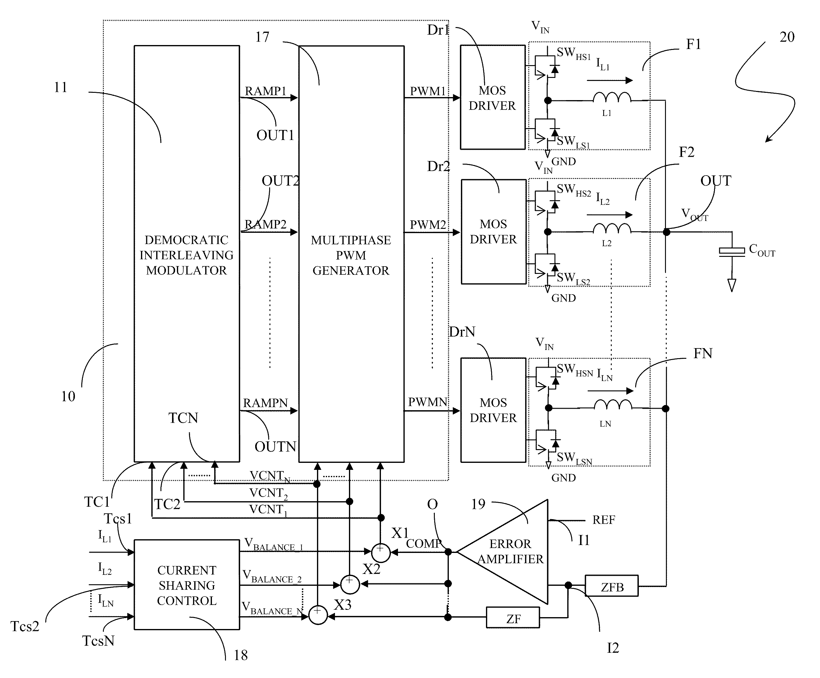
[0053]Embodiments of the present invention provide methods for controlling the turn-on of the phases of a multiphase regulator, and modulators for use in such a multiphase regulator, having such structural and functional characteristics as to overcome the limits and the drawback that affect conventional modulators. The turn-on of the phases of a multiphase regulator is regulated by establishing the reset sequence of the ramp signals being used for the generation of the PWM modulation signals of the phases through a logic that is based on the control voltages of the modulator.

[0054]One embodiment of the present invention provides a method for controlling the turn-on of multiple phases of a multiphase regulator of the interleaving type. The phases are driven to be turned on by respective modulation signals generated from corresponding ramp signals and according to a list of priorities contained in cells of a phase register. According to the method, there are tested the conditions nece...


PUM


Abstract

A method is provided for controlling turn-on of phases of a multiphase regulator. According to the method, there are tested the conditions necessary for the turn-on of a phase to be turned-on indicated by a first cell of the phase register, and in response to a positive result a corresponding ramp signal is reset. There is then tested the conditions necessary for the turn-on of a phase successive to the phase to be turned on according to the list of priorities of the phase register, and corresponding ramp signals are reset if there is a positive result. In response to no positive results of testing conditions necessary for the turn-on of all phases successive to the phase to be turned on, there is reset a ramp signal corresponding to a phase successive to a last turned on phase indicated by a last cell of the phase register.

Description

CROSS-REFERENCE TO RELATED APPLICATIONS[0001]This application is based upon and claims priority from Italian Patent Application No. MI2009A 001020, filed Jun. 10, 2009, the entire disclosure of which is herein incorporated by reference.FIELD OF THE INVENTION[0002]The present invention relates to electronic circuits, and more particularly to methods for controlling the turn-on of multiple phases of a multiphase regulator of the interleaving type and corresponding modulation systems.BACKGROUND OF THE INVENTION[0003]As is well known, microprocessors or central processing units (“CPUs”) for personal computers, workstations, and servers now require very sophisticated mechanisms for the controlling the supply voltage reference to which they are connected. These references should meet high precision requirements both under rest conditions and under load transient conditions.[0004]Suitable current or voltage controller devices are thus used that are able to supply suitable voltage reference...

Claims


Application Information

Patent Timeline
Patent Type & Authority Patents(United States)
IPC IPC(8): G05F1/00H02M3/158
CPCH02M3/1584
Inventor ZAMBETTI, OSVALDO ENRICOZAFARANA, ALESSANDRO
Owner STMICROELECTRONICS SRL
Features
  • R&D
  • Intellectual Property
  • Life Sciences
  • Materials
  • Tech Scout
  • Unparalleled Data Quality
  • Higher Quality Content
  • 60% Fewer Hallucinations
Learn More