Check patentability & draft patents in minutes with Patsnap Eureka AI!

Electrode system with shunt electrode

Active Publication Date: 2015-04-28
MEDTRONIC INC
View PDF28 Cites 2 Cited by
  • Summary
  • Abstract
  • Description
  • Claims
  • Application Information

AI Technical Summary

Problems solved by technology

One of the concerns is that, during an MRI procedure, time-varying electromagnetic fields generated by the MRI device may cause energy to be transferred to leads associated with the IMD.

Method used


Image

  • Electrode system with shunt electrode
  • Electrode system with shunt electrode
  • Electrode system with shunt electrode

Examples


Embodiment Construction

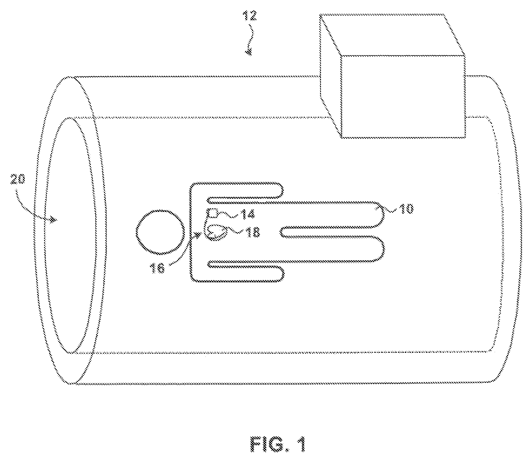
[0012]In general, the claimed invention is directed to electrode systems that include a shunt electrode. The electrode systems behave in a conventional manner under ordinary conditions, such as ordinary stimulation and sensing, in which case the shunt electrode has very little effect upon the operation of the electrode system. When high frequency current is delivered to the electrode system, however, the electrode system shunts most of the high frequency current to the shunt electrode. The shunt electrode, which has a large surface area, dissipates the resulting heat.

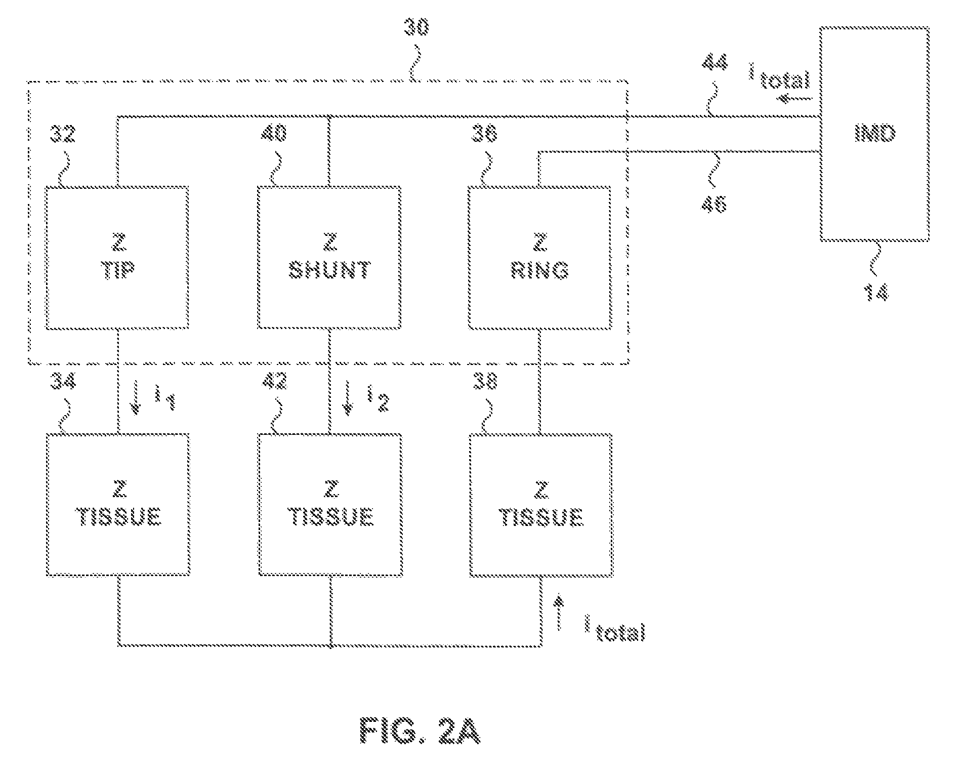
[0013]The electrode system includes a conventional electrode for sensing signals, delivering stimulations, or both. The conventional electrode and the shunt electrode are coupled to the same conductor. As a result, electrical signals conducted along the lead and through patient tissue pass through the conventional electrode and the shunt electrode in parallel. The current divides among the conventional electrode and the...


PUM


Abstract

Electrode systems that may be used with implantable medical devices such as a pacemaker, in addition to one or more conventional electrodes, include a shunt electrode. Under ordinary conditions, the shunt electrode has very little effect upon the operation of the electrode system. When high frequency current is delivered to the electrode system, however, the electrode system shunts a large share of the high frequency current to the shunt electrode. The shunt electrode, which includes a conducting material surrounded by an insulating layer, dissipates heat that may be caused by the high frequency current.

Description

FIELD OF THE INVENTION[0001]The invention relates to electrodes implantable in a human or animal body.BACKGROUND OF THE INVENTION[0002]Magnetic resonance imaging (MRI) techniques have been developed for various medical applications. MRI techniques make use of electromagnetic fields to create images of a patient. MRI techniques may allow for the generation of high-quality two- or three-dimensional images of a patient tissue, which can then be examined by a physician for diagnosis purposes. In particular, MRI techniques allow for the generation of internal images of patient's tissue, blood, flesh, organs, or the like, which can be examined to identify problems with the patient and facilitate improved patient care.[0003]MRI devices typically subject a patient to a very strong magnetic field, and then apply pulses or bursts of radio frequency (RF) radiation to an area of the patient to be imaged. The strong magnetic field generally orients the protons of the tissue of the patient in par...

Claims


Application Information

Patent Timeline
Patent Type & Authority Patents(United States)
IPC IPC(8): A61N1/37A61N1/05A61N1/08
CPCA61N1/056A61N1/057A61N1/0573A61N2001/086A61N1/086
Inventor ZEIJLEMAKER, VOLKERT A.
Owner MEDTRONIC INC
Features
  • R&D
  • Intellectual Property
  • Life Sciences
  • Materials
  • Tech Scout
  • Unparalleled Data Quality
  • Higher Quality Content
  • 60% Fewer Hallucinations
Learn More