Supercharge Your Innovation With Domain-Expert AI Agents!

Battery storing device

a battery and storage device technology, applied in the field of battery storage devices, can solve the problems of deteriorating the performance of the battery, adding further vibrations or impacts to the battery, and the battery cannot be sufficiently fixed, so as to prevent the vibration or impact of the battery performance, and facilitate the exchange of the battery

Active Publication Date: 2015-05-19
YOKOGAWA ELECTRIC CORP
View PDF18 Cites 0 Cited by
  • Summary
  • Abstract
  • Description
  • Claims
  • Application Information

AI Technical Summary

Benefits of technology

The device effectively prevents performance deterioration of batteries by securely fixing them against vibrations and impacts, allowing for easy battery exchange, regardless of size variations within standard dimensions.

Problems solved by technology

However, since the battery cannot be sufficiently fixed through only a pressing force by the coil spring, when vibrations or impacts are applied to the battery storing device, the battery moves in the battery storing device to add further vibrations or impacts to the battery.
Then, destruction or the like of a power device or a power collection mechanism in the battery may be generated to deteriorate the performance of the battery.
For this reason, even if the shock absorbing material appropriate for the size of the battery provided from a certain manufacturer is installed, when the size of the battery of another manufacturer to be stored in the battery storing device is small, the battery cannot be sufficiently fixed, and the vibrations or impacts may be applied to the battery and cause performance deterioration of the battery.
On the other hand, when the size of the battery of the other manufacturer to be stored in the battery storing device is large, the battery cannot be stored in the battery storing device, or a large force is needed upon insertion and extraction of the battery and thus battery exchange cannot be easily performed.

Method used


Image

  • Battery storing device
  • Battery storing device
  • Battery storing device

Examples


Embodiment Construction

[0033]The present invention will be now described herein with reference to illustrative preferred embodiments. Those skilled in the art will recognize that many alternative preferred embodiments can be accomplished using the teaching of the present invention and that the present invention is not limited to the preferred embodiments illustrated herein for explanatory purposes.

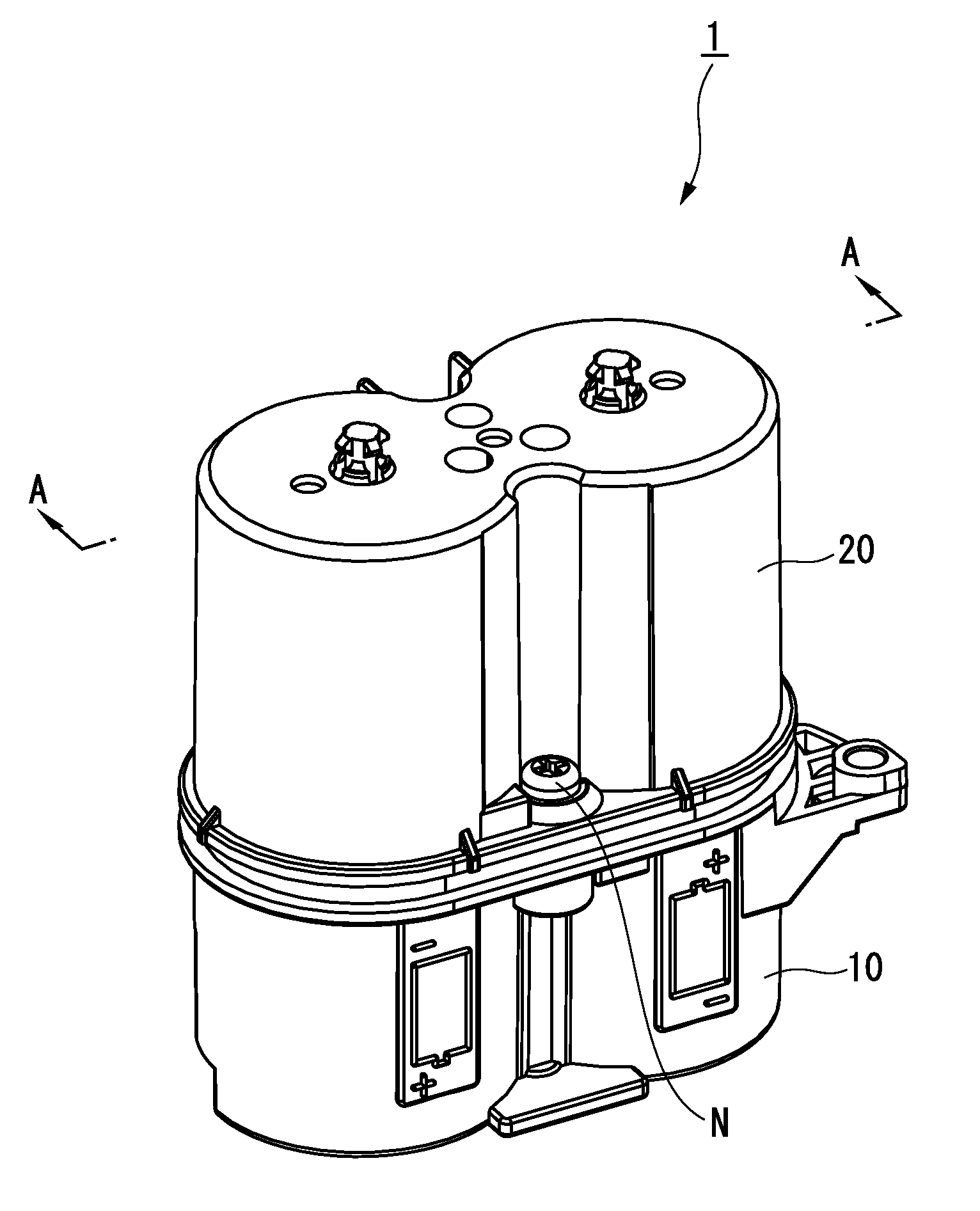
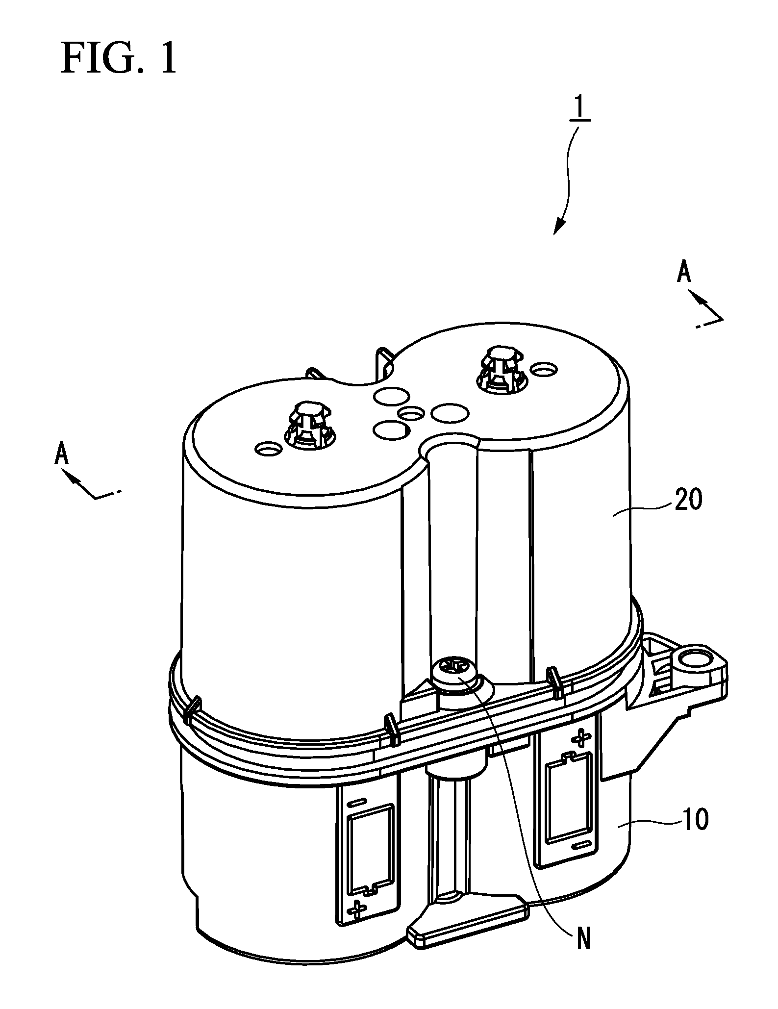
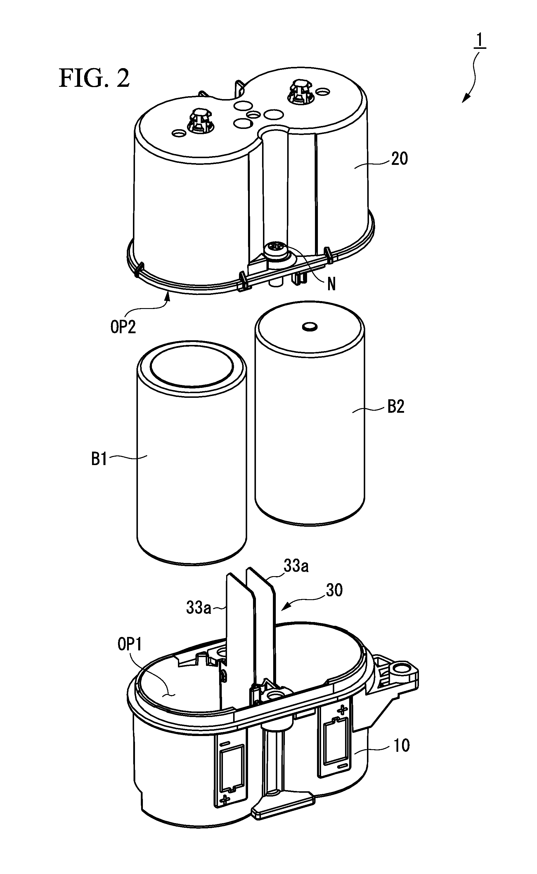
[0034]A battery storing device in accordance with a first preferred embodiment of the present invention will be described in detail. FIG. 1 is a perspective view showing the battery storing device in accordance with the first preferred embodiment of the present invention. As shown in FIG. 1, a battery storing device 1 includes a first case member 10, a second case member 20, and a screw N configured to fix the first case member 10 and the second case member 20. The first case member 10 is a battery case main body configured to store a battery. The second case member 20 is a cover of the battery case. The first c...


PUM

PropertyMeasurementUnit
lengthaaaaaaaaaa
lengthaaaaaaaaaa
diameteraaaaaaaaaa

Abstract

A battery storing device may include: a case member having a positive terminal and a negative terminal and configured to store a battery therein; a positive pole coil spring in contact with a positive electrode of the battery; a negative pole coil spring in contact with a negative electrode of the battery; and a first support comprising a sidewall support section having an elastic force that is able to fix the battery while absorbing a size difference of the battery allowed according to a standard, and configured to support a sidewall of the battery.

Description

BACKGROUND OF THE INVENTION[0001]1. Field of the Invention[0002]The present invention relates to a battery storing device configured to store a battery.[0003]Priority is claimed on Japanese Patent Application No. 2011-260315, filed Nov. 29, 2011, the content of which is incorporated herein by reference.[0004]2. Description of the Related Art[0005]All patents, patent applications, patent publications, scientific articles, and the like, which will hereinafter be cited or identified in the present application, will hereby be incorporated by reference in their entirety in order to describe more fully the state of the art to which the present invention pertains.[0006]In a plant or a factory, a sensor apparatus such as a differential pressure transmitter or a temperature transmitter, a valve apparatus such as a flow rate control valve or an on-off valve, an actuator apparatus such as a fan or a motor, and other field devices are installed numerously. A conventional field apparatus is conn...

Claims


Application Information

Patent Timeline
Patent Type & Authority Patents(United States)
IPC IPC(8): H01M2/10H01M50/213H01M50/227H01M50/262H01M50/264H01M50/267H01M50/296
CPCH01M2/1072H01M2/1022H01M2/105H01M2/1027Y02E60/10H01M50/267H01M50/213H01M50/264H01M50/296H01M50/227H01M50/262
Inventor IGARASHI, YOUICHI
Owner YOKOGAWA ELECTRIC CORP
Features
  • R&D
  • Intellectual Property
  • Life Sciences
  • Materials
  • Tech Scout
  • Unparalleled Data Quality
  • Higher Quality Content
  • 60% Fewer Hallucinations
Learn More