Check patentability & draft patents in minutes with Patsnap Eureka AI!

Multi-piece-array and method of manufacturing the same

a multi-piece array and piece technology, applied in the field of multi-piece arrays, can solve the problems of irregular chipping, deformation of the peripheral portions of the wiring board adjacent to the blade, etc., and achieve the effects of improving the dimensional accuracy of the front surface and the back surface of the wiring board portion, easy cutting of the multi-piece array, and excellent shape and dimensional accuracy

Inactive Publication Date: 2015-06-02
NGK SPARK PLUG CO LTD
View PDF5 Cites 0 Cited by
  • Summary
  • Abstract
  • Description
  • Claims
  • Application Information

AI Technical Summary

Benefits of technology

This approach prevents inadvertent chipping, cracking, or breaking during division and improves the shape and dimensional accuracy of the wiring boards, allowing for easier cutting and reliable manufacturing by suppressing microcrack generation and preventing ceramic or metal dust from reentering the grooves.

Problems solved by technology

However, there has been a problem in that the peripheral portions of the wiring board regions adjacent to the blade are deformed by the load of the blade when the blade is made to penetrate the soft green sheet laminate body.
For this reason, there has been a problem in that irregular chipping occurs from the vicinity of the dividing grooves in the following the firing step or a plating step subsequent to the firing step or cracking or breaking occurs on the individual wiring boards at the time of division in a dividing step to be further performed.

Method used


Image

  • Multi-piece-array and method of manufacturing the same
  • Multi-piece-array and method of manufacturing the same
  • Multi-piece-array and method of manufacturing the same

Examples


Embodiment Construction

[0043]Embodiments of the invention will be described below.

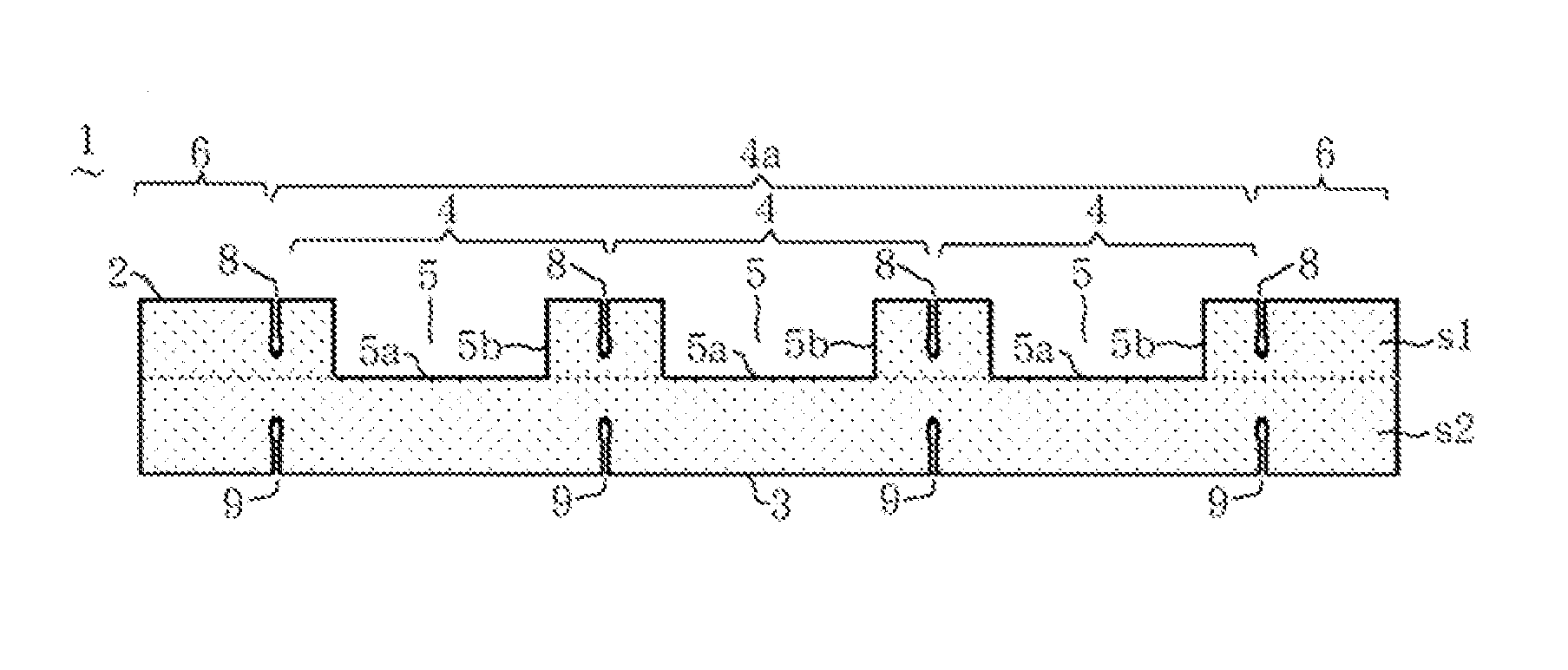
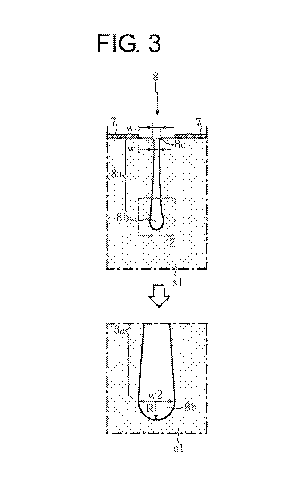
[0044]FIG. 1 is a plan view of a multi-piece-array 1 according to an embodiment of the invention. FIG. 2 is a vertical cross-sectional view taken along line X-X of FIG. 1, and FIG. 3 is a partially enlarged cross-sectional view taken along line Y-Y ofFIG. 1 and a partially enlarged view of a portion Z shown in FIG. 3 by a dashed-dotted line.

[0045]As shown in FIGS. 1 and 2, the multi-piece-array 1 is formed by laminating upper and lower, that is, two (a plurality of) ceramic layers s1 and s2 made of, for example, alumina (ceramic), and has a front surface (main surface) 2 and a back surface (main surface) 3 that have a rectangular shape in plan view. Further, the multi-piece-array 1 includes a product region 4a where a plurality of wiring board portions 4 having a rectangular shape in plan view are arranged in a matrix, an edge portion 6 that has the shape of a rectangular frame and is positioned along the periphery of the pr...


PUM

PropertyMeasurementUnit
radiusaaaaaaaaaa
radiusaaaaaaaaaa
radiusaaaaaaaaaa

Abstract

A multi-piece-array formed by laminating a plurality of ceramic layers includes: a product region where a plurality of wiring board portions having a rectangular shape in plan view and including cavities are arranged in matrix; a redundant portion that is positioned along a periphery of the product region; and dividing grooves that are formed on a front surface and / or a back surface along a boundary between the wiring board portions and a boundary between the wiring board portion and the redundant portion. A deepest portion of the dividing groove has an arc shape and the dividing groove includes a middle portion, and a width of the deepest portion is greater than a width of the groove inlet and a width of the middle portion is equal to or less than the width of the groove inlet.

Description

TECHNICAL FIELD[0001]The present invention relates to a multi-piece-array in which it is difficult for chipping, cracking, or breaking to occur from the vicinity of dividing grooves of the wiring hoard at the time the multi-piece-array is divided into individual pieces or before being divided into individual pieces, and which has high reliability, and a method of reliably manufacturing the wiring board.BACKGROUND ART[0002]When a plurality of ceramic wiring boards are manufactured with multi-piece-array, conventionally, a green sheet laminate body has been formed by laminating and press-bonding a plurality of green sheets where a conductor layer is formed on at least one of a front surface and a back surface of a green sheet laminate body, dividing grooves have been formed so as to have a predetermined depth along boundaries between individual wiring board regions of the laminate body by a blade (die), and a plurality of ceramic wiring boards have been simultaneously manufactured by ...

Claims


Application Information

Patent Timeline
Patent Type & Authority Patents(United States)
IPC IPC(8): H01K1/02B32B3/30H05K1/03H05K3/00
CPCH05K1/0306H05K3/0052B32B3/30H05K3/00Y10T428/15Y10T156/10H05K2201/09036H05K2201/0909H05K1/09H05K3/0097H05K2201/09154H05K2201/09863H05K1/02
Inventor YOSHIDA, YOSHITAKAYAMAMOTO, HIROAKI
Owner NGK SPARK PLUG CO LTD
Features
  • R&D
  • Intellectual Property
  • Life Sciences
  • Materials
  • Tech Scout
  • Unparalleled Data Quality
  • Higher Quality Content
  • 60% Fewer Hallucinations
Learn More