Supercharge Your Innovation With Domain-Expert AI Agents!

Laser light source

a laser light source and laser technology, applied in the direction of laser details, semiconductor lasers, optical resonator shape and construction, etc., can solve the problem of complex structure of optical resonators

Active Publication Date: 2015-10-06
NEC CORP
View PDF7 Cites 0 Cited by
  • Summary
  • Abstract
  • Description
  • Claims
  • Application Information

AI Technical Summary

Benefits of technology

[0013]According to the present invention, it is possible to provide a laser light source that outputs light having a narrow spectrum line-width using an optical resonator of a simple structure.

Problems solved by technology

However, the inventor has found the following various problems.
Japanese Unexamined Patent Publication No. 2012-33807 discloses that a reduction in line-width is performed without increasing a resonator length by adjusting the amount of detuning of the optical filter which is inserted into the optical resonator, but the structure of the optical resonator becomes complicated.

Method used


Image

  • Laser light source
  • Laser light source
  • Laser light source

Examples


first embodiment

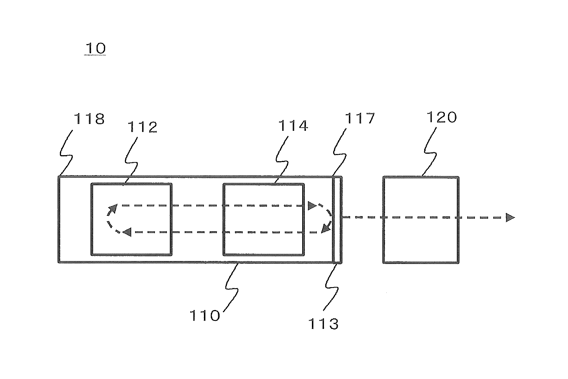
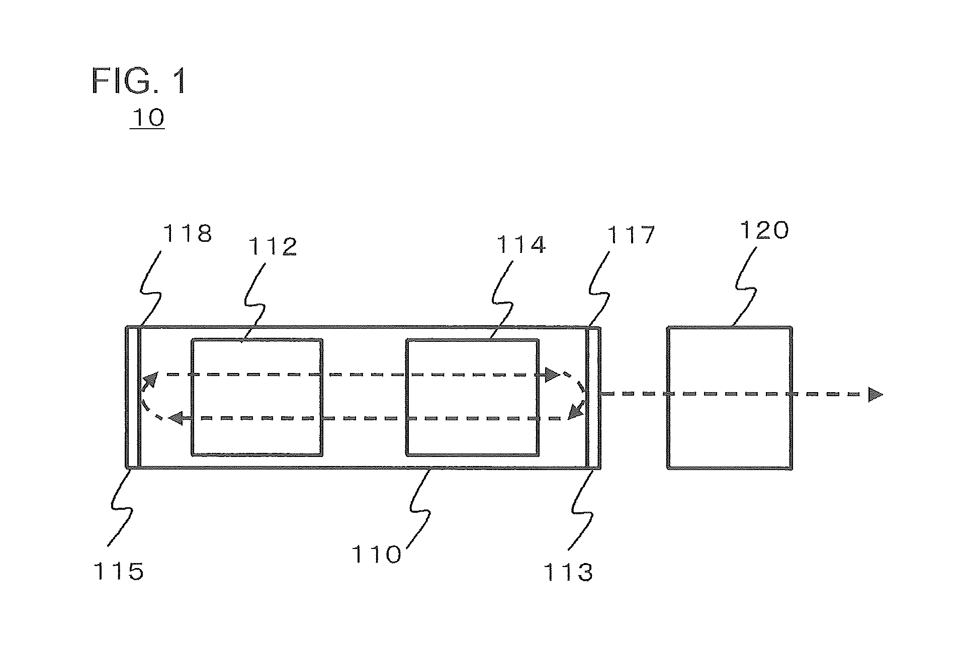
[0022]FIG. 1 is a diagram illustrating a structure of a laser light source 10 according to a first embodiment. In the drawing, dashed lines schematically show a path of light. According to the present embodiment, the laser light source 10 includes an optical resonator 110 and a first optical filter 120. The first optical filter 120 is provided outside the optical resonator 110, and does not constitute an optical resonator structure.

[0023]For example, antireflection coating is performed on the optical resonator 110 side of the first optical filter 120 and on the surface on the opposite side thereto, and a reflection structure in which light is reflected in the direction to the optical resonator 110 is not present on an optical path of light after passing through the first optical filter 120.

[0024]A detailed description will be given below.

[0025]The first optical filter 120 is provided outside the optical resonator 110, and transmits only light having a desired frequency in light whic...

second embodiment

[0059]FIG. 4 is a diagram illustrating a configuration of a laser light source 10 according to a second embodiment. The laser light source 10 according to the present embodiment includes an optical isolator 130, an optical monitor 140, and a control unit 150 in addition to the configuration of the laser light source 10 according to the first embodiment, and includes a phase adjustment unit 116 in the optical resonator 110. Besides, except for points described below, the laser light source 10 according to the present embodiment is the same as the laser light source 10 according to the first embodiment.

[0060]The laser light source 10 according to the present embodiment includes the optical resonator 110, the optical isolator 130, the first optical filter 120, the optical monitor 140, and the control unit 150. The optical resonator 110 includes the second optical filter 112, the phase adjustment unit 116, and the gain unit 114 therein. The first reflecting mirror 113 is provided on the...


PUM


Abstract

A laser light source includes an optical resonator and a first optical filter. The first optical filter is provided outside the optical resonator, and does not constitute an optical resonator structure. For example, antireflection coating is performed on the optical resonator side of the first optical filter and on a surface on the opposite side thereto, and a reflection structure in which light after passing through the first optical filter is reflected in the direction to the optical resonator is not present on an optical path of the light.

Description

[0001]This application is based on Japanese patent application No. 2013-182789, the content of which is incorporated hereinto by reference.BACKGROUND[0002]1. Technical Field[0003]The present invention relates to a laser light source.[0004]2. Related Art[0005]As light sources that emit laser light, laser light sources that emit light having a narrow spectrum line-width are required.[0006]The line-width of laser light is inversely proportional to the square of a resonator length when a loss of a waveguide constituting an optical resonator is sufficient small. On the other hand, the line-width is inversely proportional to the resonator length when the waveguide loss is large.[0007]Electronics Letters, vol. 21, No. 3, pp 113-115, 1985 discloses that the contraction of a spectrum line-width is achieved by increasing the length of an optical resonator.[0008]However, the inventor has found the following various problems. When the length of the optical resonator is increased, adjacent longi...

Claims


Application Information

Patent Timeline
Patent Type & Authority Patents(United States)
IPC IPC(8): H01S3/08
CPCH01S3/08H01S3/08018H01S3/08022H01S3/08027H01S3/08031H01S5/0078H01S5/06256
Inventor OKAMOTO, TAKESHI
Owner NEC CORP
Features
  • R&D
  • Intellectual Property
  • Life Sciences
  • Materials
  • Tech Scout
  • Unparalleled Data Quality
  • Higher Quality Content
  • 60% Fewer Hallucinations
Learn More