Check patentability & draft patents in minutes with Patsnap Eureka AI!

Hydrodynamic energy generation system with energy recovery and levering subsystem

a hydrodynamic energy and subsystem technology, applied in the field of energy production, can solve the problems of high cost to establish, lack of aesthetic appeal, and difficulty in widespread acceptance of alternative power generation techniques

Inactive Publication Date: 2015-10-13
HANNA IBRAHIM
View PDF19 Cites 8 Cited by
  • Summary
  • Abstract
  • Description
  • Claims
  • Application Information

AI Technical Summary

Benefits of technology

The patent describes a hydrodynamic energy generation system that can produce electricity from water movement. The system includes a housing with a valve for regulating water flow, a water wheel, a reservoir for holding water, a pump for removing water, and a water jet for moving the water wheel and generating power. A control processor is used to manage the valve, pump, and water jet. The patent has technical benefits in generating energy from water movement, which can provide a sustainable and efficient way to generate energy.

Problems solved by technology

Despite the fact that they are considerably more environmentally-friendly, these alternative power generation techniques have struggled to gain widespread acceptance due to their inefficiencies in generating power, their high cost to establish in comparison to existing fossil fuel technology and their lack of aesthetic appeal (such as wind farms).
Although hydroelectric power is one of the cleanest and most environmentally-friendly sources of energy, it also has the capability to alter or damage its surroundings.
In some forms of present use, among the main problems that have been demonstrated by hydroelectric power is significant change in water quality.
Because of the nature of hydroelectric systems, the water used in the system can often take on a higher temperature, lose oxygen content, experience siltation, and gain in phosphorus and nitrogen content.
Another major problem with hydroelectric power is the obstruction of a body of water, such as a river, for aquatic life.
When used in the context of a flowing body of water, such as a river, a hydroelectric plant can obstruct the natural migration of aquatic life.

Method used


Image

  • Hydrodynamic energy generation system with energy recovery and levering subsystem
  • Hydrodynamic energy generation system with energy recovery and levering subsystem
  • Hydrodynamic energy generation system with energy recovery and levering subsystem

Examples


Embodiment Construction

[0026]The following detailed description refers to the accompanying drawings. Wherever possible, the same reference numbers are used in the drawings and the following description to refer to the same or similar elements. While embodiments of the invention may be described, modifications, adaptations, and other implementations are possible. For example, substitutions, additions, or modifications may be made to the elements illustrated in the drawings, and the methods described herein may be modified by substituting, reordering, or adding stages to the disclosed methods. Accordingly, the following detailed description does not limit the invention. Instead, the proper scope of the invention is defined by the appended claims.

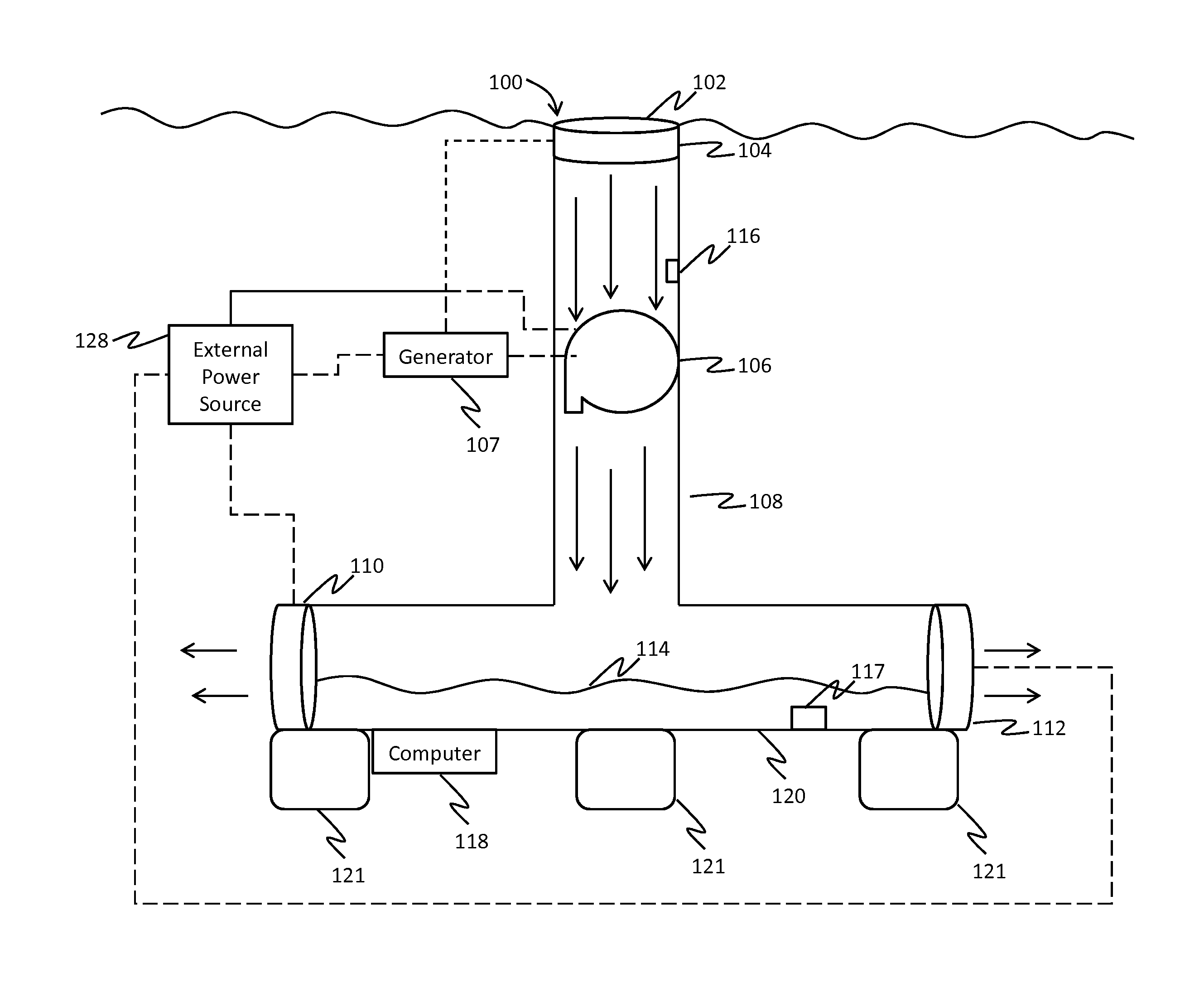
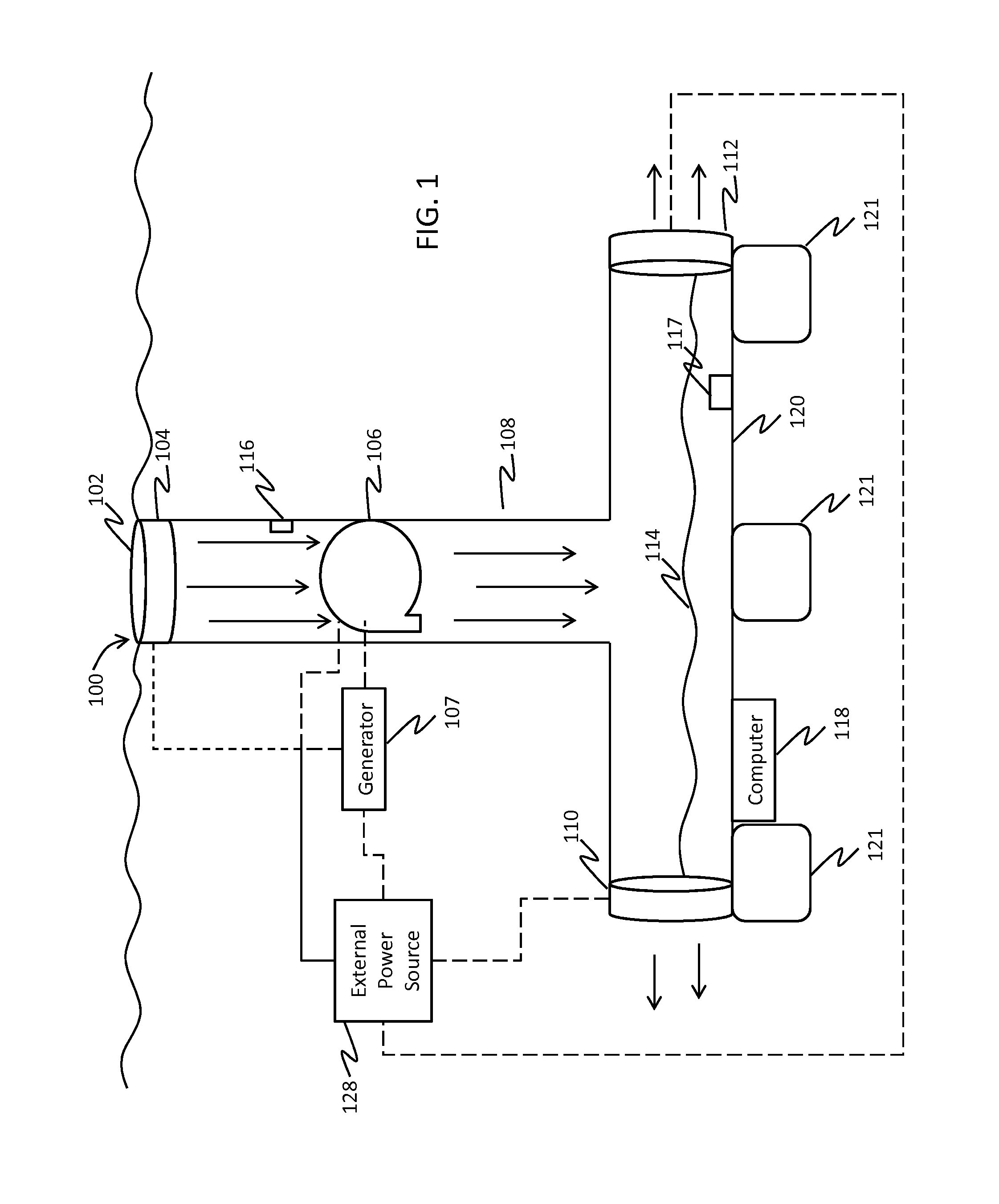
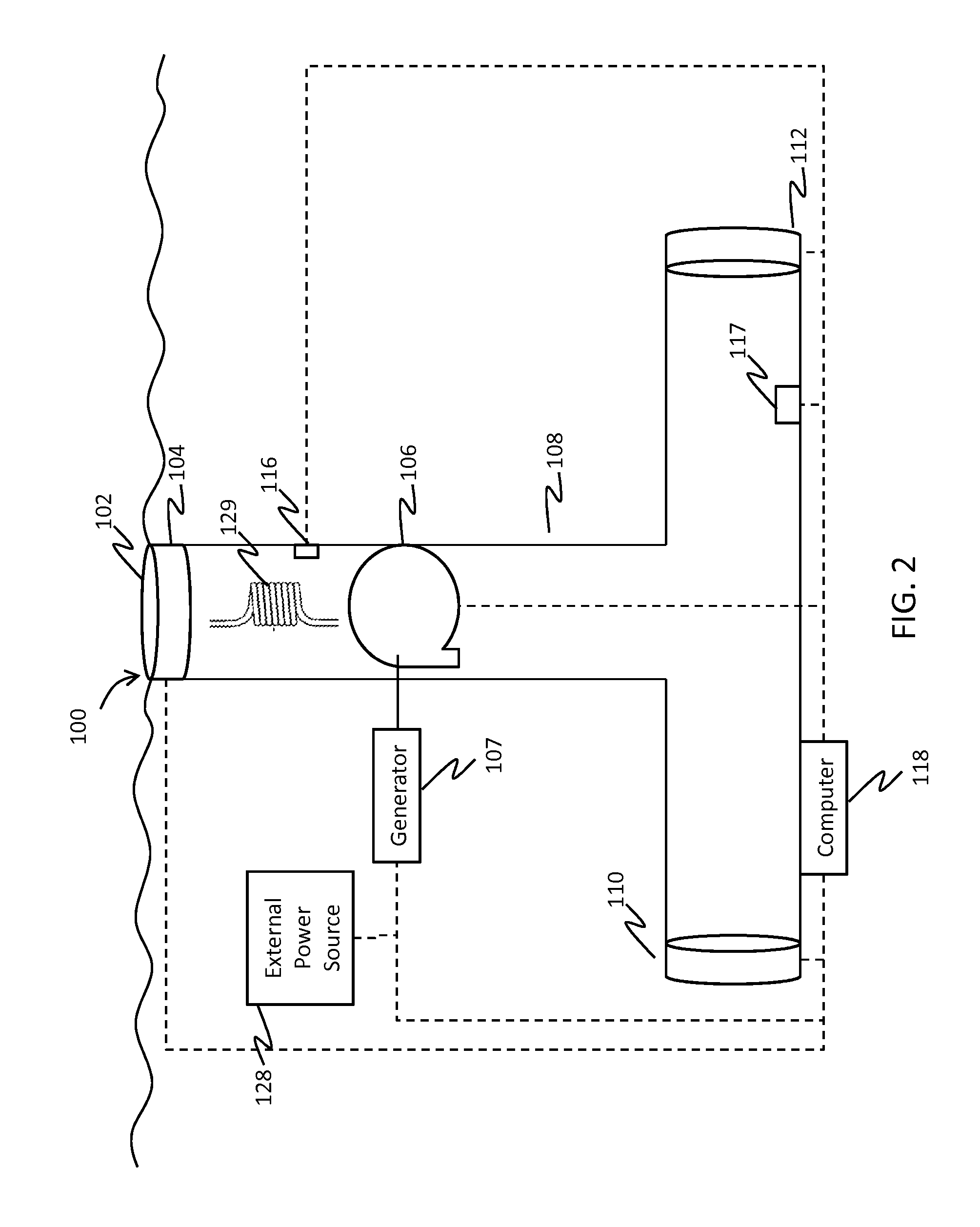
[0027]In accordance with the embodiments described herein, a hydrodynamic energy generation system is disclosed that overcomes the problems with the prior art as discussed above, by providing an energy generation system that utilizes clean, renewable energy and does...


PUM


Abstract

The hydrodynamic energy generation system includes a vertically aligned housing comprising a hollow interior and an opening at a top, wherein the housing is at least partially submerged in a body of water, a valve coupled to a top of the housing for regulating an amount of water that enters the opening at the top and falls into the housing, wherein the valve is located under a water line, a water wheel coupled to a generator that produces electrical power when the water wheel is moved by water that falls into the housing, a reservoir located below the water wheel for holding water, a pump for removing water from the reservoir, and a water jet for receiving water from the pump and jettisoning water towards the water wheel, so as to move the water wheel and cause the generator to produce electrical power.

Description

CROSS-REFERENCE TO RELATED APPLICATIONS[0001]This patent application is a continuation in part and claims priority to utility patent application Ser. No. 14 / 258,716 filed Apr. 22, 2014 and entitled “Hydrodynamic Energy Generation System with Energy Recovery and Levering System”, which is a continuation in part and claims priority to utility patent application Ser. No. 14 / 195,133 filed Mar. 3, 2014 and entitled “Hydrodynamic Energy Generation System”, which claims priority to provisional patent application No. 61 / 925,828 filed Jan. 10, 2014 and entitled “Hydrodynamic Energy Generation System.” Application Ser. Nos. 14 / 258,716, 14 / 195,133 and 61 / 925,828 are hereby incorporated by reference in their entirety.STATEMENT REGARDING FEDERALLY SPONSORED RESEARCH OR DEVELOPMENT[0002]Not Applicable.INCORPORATION BY REFERENCE OF MATERIAL SUBMITTED ON A COMPACT DISC[0003]Not Applicable.FIELD OF THE INVENTION[0004]The present invention relates to the field of energy production, and more specifica...

Claims


Application Information

Patent Timeline
Patent Type & Authority Patents(United States)
IPC IPC(8): F01D15/00F01D15/10F03B17/02F03B13/06F03B17/00
CPCF01D15/10F03B13/06F03B17/02F03B17/005Y10S415/916F05B2240/97Y02E10/20Y02E60/16
Inventor HANNA, IBRAHIM
Owner HANNA IBRAHIM
Features
  • R&D
  • Intellectual Property
  • Life Sciences
  • Materials
  • Tech Scout
  • Unparalleled Data Quality
  • Higher Quality Content
  • 60% Fewer Hallucinations
Learn More