Medical connector
a technology of medical devices and connectors, applied in the field of medical devices, can solve the problems of dangerous misconnection, serious patient injuries and deaths, and the wrong route of medication or other fluids to be delivered,
- Summary
- Abstract
- Description
- Claims
- Application Information
AI Technical Summary
Benefits of technology
Problems solved by technology
Method used
Image
Examples
second embodiment
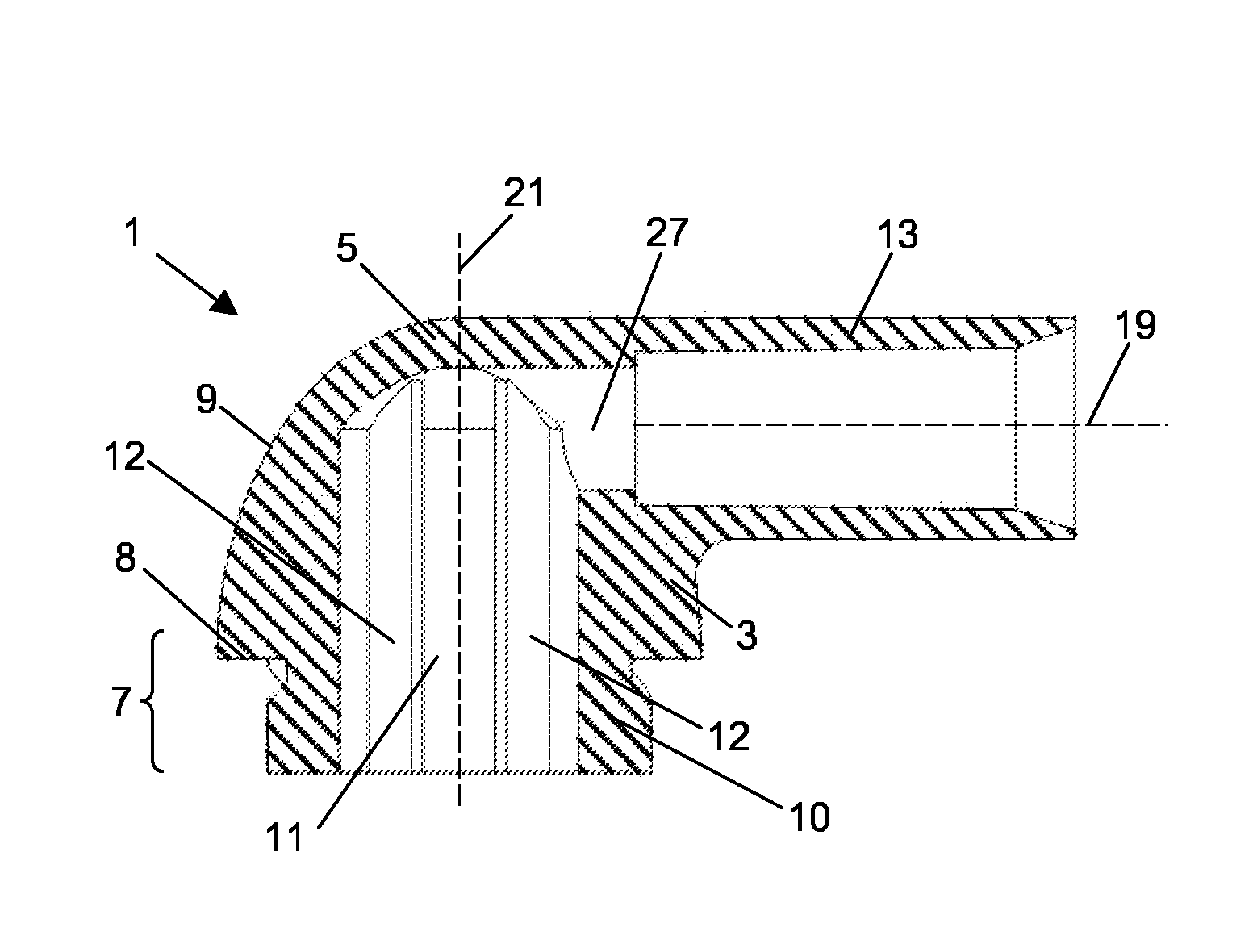
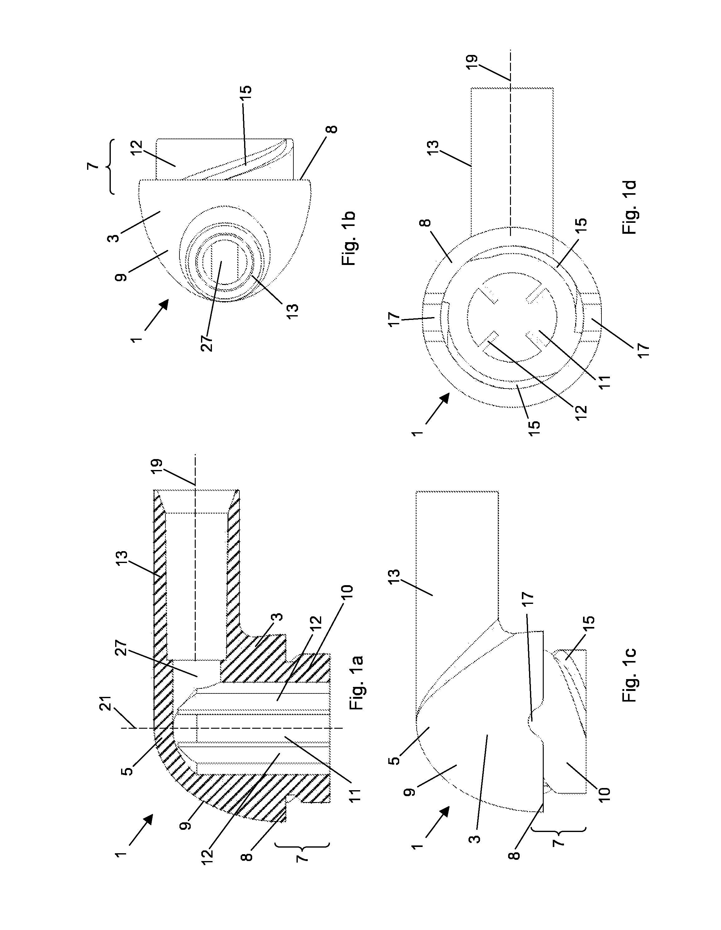
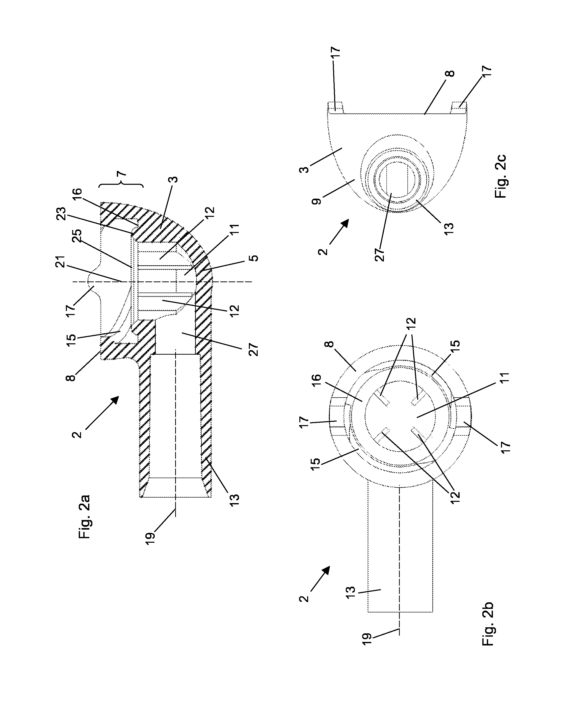
[0065]FIGS. 2a -2c show a cross section view, a top view, and a side view, respectively, of the connector according to the invention, the “female” connector 2. Most of the features of the “female” connector 2 are identical with the features of the “male” connector 1, therefore only the differences will be described herein.
[0066]In the second embodiment two thread sectors 15 are located on the inner surface of the coupling portion 7 from the coupling surface 8 to a stop surface 16 positioned inside the internal cavity 11. Thus, the “female” connector 2 does not comprise a cylindrical extension 10 as the “male” connector 1. The two thread sectors 15 are shown as protrusions (see FIGS. 2a and 2b ). Alternatively, they can be formed as recesses. In any case, the thread sectors 15 of the “female” connector 2 must be complementary to the thread sectors 15 of the “male” connector 1.
[0067]Furthermore, the barriers 12 formed as radial walls extend only from the stop surface 16 into the inter...
third embodiment
[0076]The two wing elements 20 extend from the outer surface 9 of the body 3 and also into the area where the tube mating portion 13 abuts the body 3. The purpose of the wing elements 20 is to provide an ergonomically convenient point of action for the engagement and disengagement of two complementary connectors as will be described below. Therefore, the shown configuration of the third embodiment comprises a smooth transition between the wing elements 20 and the respective elements of the body 3 and the tube mating portion 13.
[0077]With respect to FIGS. 4c and 4d it can be seen that the two wing elements 20 are not fully symmetric: one wing element 20 extends just below the plane of the coupling surface 8, and the other wing element 20 extends beyond that plane up to the plane of the opening of the cylindrical extension 10 wherein a gap is provided between the cylindrical extension 10 and the other wing element 20. One of the reasons for this asymmetry is the required mutual engage...
fourth embodiment
[0080]The two wing elements 20 extend from the outer surface 9 of the body 3 and also into the area where the tube mating portion 13 abuts the body 3. The purpose of the wing elements 20 is to provide an ergonomically convenient point of action for the engagement and disengagement of two complementary connectors as will be described below. Therefore, the shown configuration of the fourth embodiment comprises a smooth transition between the wing elements 20 and the respective elements of the body 3 and the tube mating portion 13.
[0081]With respect to FIGS. 5c and 5d it can be seen that the two wing elements 20 are not fully symmetric: one wing element 20 extends up to the plane of the stop surface 16, and the other wing element 20 extends beyond that plane up to the plane of the coupling surface 8.
[0082]FIGS. 6a to 6d show a connector system according to the invention with a “male” connector according to the third embodiment of the invention being coupled to a “female” connector acco...
PUM
| Property | Measurement | Unit |
|---|---|---|
| inner diameter | aaaaa | aaaaa |
| diameters | aaaaa | aaaaa |
| angle | aaaaa | aaaaa |
Abstract
Description
Claims
Application Information
 - R&D Engineer
- R&D Manager
- IP Professional
- Industry Leading Data Capabilities
- Powerful AI technology
- Patent DNA Extraction
Browse by: Latest US Patents, China's latest patents, Technical Efficacy Thesaurus, Application Domain, Technology Topic, Popular Technical Reports.
© 2024 PatSnap. All rights reserved.Legal|Privacy policy|Modern Slavery Act Transparency Statement|Sitemap|About US| Contact US: help@patsnap.com


