Check patentability & draft patents in minutes with Patsnap Eureka AI!

DFT approach to enable faster scan chain diagnosis

a scan chain and diagnostic technology, applied in the field of integrated circuits, can solve the problems of cumbersome debugging, inability to use design support tools, and high cost and time consumption of debugging techniques, and achieve the effect of facilitating faster scan chain diagnosis

Active Publication Date: 2016-01-19
TEXAS INSTR INC
View PDF9 Cites 2 Cited by
  • Summary
  • Abstract
  • Description
  • Claims
  • Application Information

AI Technical Summary

Benefits of technology

Facilitates faster and more efficient scan chain diagnosis by identifying and bypassing defective logic circuits, reducing the need for expensive debugging techniques and design support tools, thereby improving product yield and reducing debugging time.

Problems solved by technology

Any defect in the scan chains become cumbersome to debug.
These debugging techniques are expensive and time consuming.
In case of a scan chain failure, design support tools which know the whole design structure are required to use ATPG tools, and these design support tools are not available either.

Method used


Image

  • DFT approach to enable faster scan chain diagnosis
  • DFT approach to enable faster scan chain diagnosis
  • DFT approach to enable faster scan chain diagnosis

Examples


Embodiment Construction

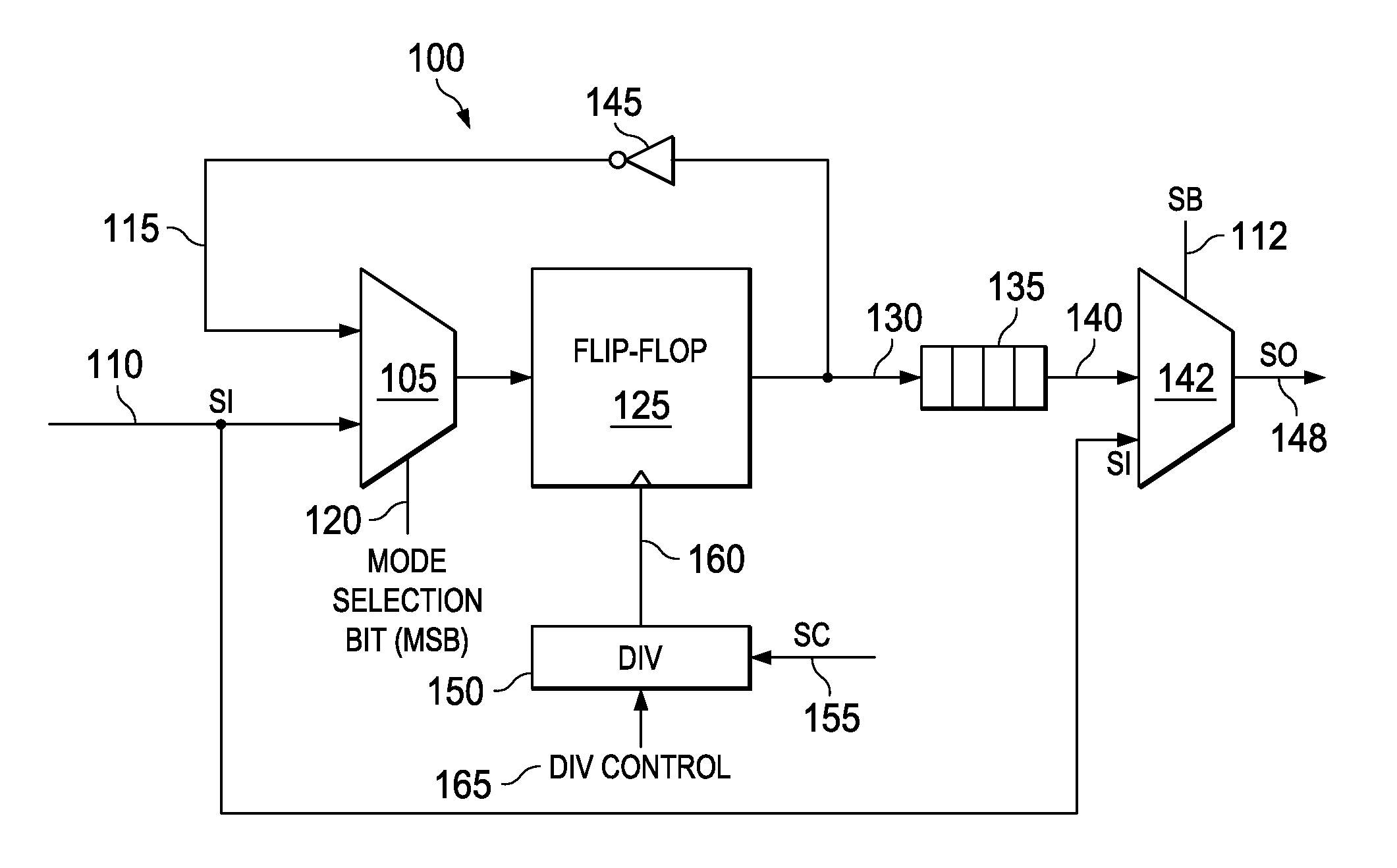
[0012]FIG. 1 illustrates a schematic of a circuit 100 for diagnosing a plurality of logic circuits according to an embodiment. The circuit 100 includes a first multiplexer 105 that receives a scan data input SI 110 and an inverted feedback signal 115. A mode selection bit (MSB) 120 is received at the first multiplexer 105. An output of the first multiplexer 105 is received by a flip-flop 125. The flip-flop 125 generates a scan pattern on line 130. A plurality of logic circuits 135 generates a logic output on line 140 in response to the scan pattern received on line 130. The plurality of logic circuits 135 is connected in a scan chain. In one of the embodiments, the plurality of logic circuits 135 is any sequential circuit known in the art such as flip-flops. The length of the scan chain is defined by the number of logic circuits connected sequentially. In one embodiment, if the number of flip flops connected in scan chain is 10, then the scan chain length is 10. The inverter 145 gen...


PUM


Abstract

A circuit that facilitates faster diagnosis of plurality of logic circuits connected in a scan chain is provided. The circuit includes a first multiplexer that receives a scan data input. A flip-flop is coupled to an output of the first multiplexer and generates a scan pattern. An inverter generates an inverted feedback signal in response to the scan pattern. The inverted feedback signal is provided to the first multiplexer. A plurality of logic circuits is connected in a scan chain and generates a logic output in response to the scan pattern. A bypass multiplexer is coupled to the plurality of logic circuits. The bypass multiplexer generates a scan output in response to the logic output, the scan data input and a segment bypass input.

Description

TECHNICAL FIELD[0001]Embodiments of the disclosure relate to integrated circuits and more particularly to diagnosing a scan chain failure in an integrated circuit (IC).BACKGROUND[0002]Design for test (DFT) approach is a scan chain based design for testing integrated circuits. Scan chain based design is a preferred mechanism for diagnosis of manufacturing defects. Scan chain based diagnosis is fast and efficient for large integrated circuits thus improving the product yield. The scan chain based diagnosis identifies root cause of logic failure in a circuit in the IC. During IC test, the scan chains are also tested to ensure that scan chains are defect free. Any defect in the scan chains become cumbersome to debug. Conventional method of debugging scan chains includes SOM (scanning optical microscopy) or EMMI (emission microscopy). These debugging techniques are expensive and time consuming. Pattern dependent failure diagnosis is also used to debug scan chain defects. Automatic test p...

Claims


Application Information

Patent Timeline
Patent Type & Authority Patents(United States)
IPC IPC(8): G01R31/3185
CPCG01R31/318536G01R31/318552G01R31/318563G01R31/318555G01R31/31858G01R31/318541
Inventor MITTAL, RAJESH KUMARKURIAN, CHARLESPODDUTUR, SUMANTH REDDY
Owner TEXAS INSTR INC
Features
  • R&D
  • Intellectual Property
  • Life Sciences
  • Materials
  • Tech Scout
  • Unparalleled Data Quality
  • Higher Quality Content
  • 60% Fewer Hallucinations
Learn More