Supercharge Your Innovation With Domain-Expert AI Agents!

Optical pickup device

a pickup device and optical technology, applied in the field of optical pickup devices, can solve the problems of inability to function, defective wires, excessive deformation of resilient wires, etc., and achieve the effect of preventing excessive deformation of resilient supporting members

Active Publication Date: 2016-02-16
ALPINE ELECTRONICS INC
View PDF6 Cites 0 Cited by
  • Summary
  • Abstract
  • Description
  • Claims
  • Application Information

AI Technical Summary

Benefits of technology

This design prevents excessive deformation of resilient supporting members and adhesion of the lens holder to the unit chassis, ensuring accurate disk detection and type identification, even under external forces and high-temperature conditions.

Problems solved by technology

Therefore, in a step that is executed after, for example, the resilient wires, the lens holder, and the focus correcting mechanism have been mounted on the base member and before the base member is mounted at the optical chassis, if an external force accidentally acts upon the lens holder, the resilient wires may become excessively bent due to the movement of the lens holder to a position where it passes the inside of the through-hole.
If the flexing amount of the resilient wires at this time goes beyond a resilience region and exceeds a yield point, the resilient wires undergo plastic deformation and become defective wires that are incapable of functioning.
However, the use of such a structure gives rise to new problems such as those described below.
During this operation, if the lens holder even temporarily adheres to the base member, an error occurs in the aforementioned detections.
This causes an erroneous determination that the disk does not exist or malfunctions, such as a discharge of the disk to the outside of the optical pickup device without identifying the disk type.
However, when the resilient wires that are secured to the lens holder are to be mounted at the base member, it is difficult to position with high precision the optical axis of the objective lens held by the lens holder with respect to the base member.
Therefore, even if flux used for solder adheres to the lens holder, the problem that the lens holder adheres to the unit chassis in a high-temperature environment no longer occurs.

Method used


Image

  • Optical pickup device
  • Optical pickup device
  • Optical pickup device

Examples


Embodiment Construction

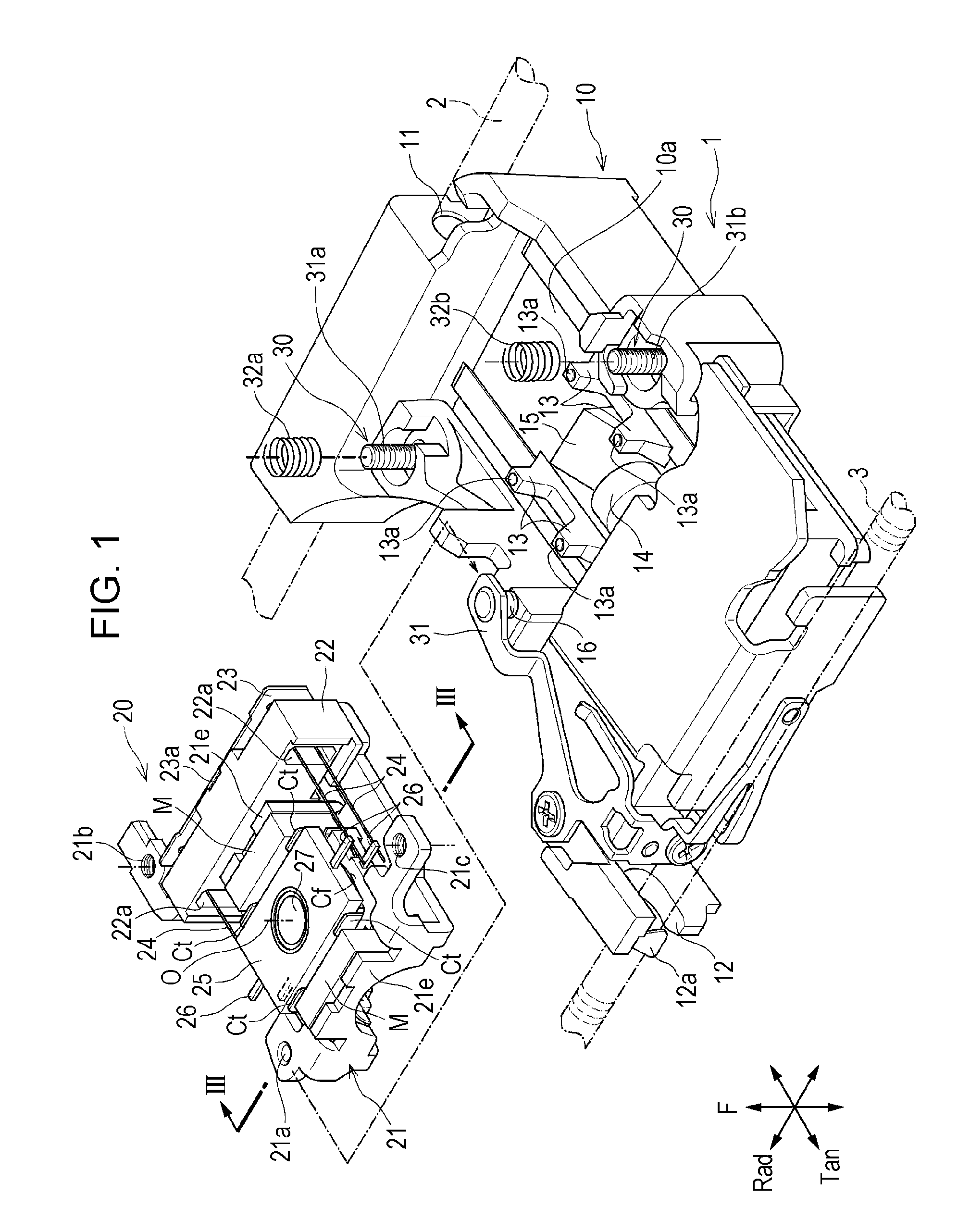
[0029]An optical pickup device 1 according to an embodiment of the present invention shown in FIG. 1 is mounted on an optical disk device. The optical disk device includes a turntable. Various types of optical disks (recording media), such as a CD or a DVD, are placed on the turntable and rotationally driven. The optical pickup device 1 reproduces information recorded on a recording surface of an optical disk or writes information to the recording surface.

[0030]The optical pickup device 1 shown in FIG. 1 includes a movable base 10. The movable base 10 is formed by injection molding with, for example, polyphenylene sulfide (PPS) resin or by die casting with a lightweight metal material, such as aluminum. A reference bearing 11 and a driving bearing 12 are formed in the movable base 10. At the optical disk device, a guide shaft 2 and a drive screw shaft 3 extend parallel to each other. The reference bearing 11 is slidably inserted onto the guide shaft 2. An engaging portion 12a of the...


PUM

PropertyMeasurementUnit
resilientaaaaaaaaaa
resilienceaaaaaaaaaa
yield pointaaaaaaaaaa

Abstract

An optical pickup device is one in which a lens holder is held by a movable base by using a resilient wire. A restricting abutting portion is formed at a lower portion of the lens holder. When the lens holder moves excessively downward, the restricting abutting portion comes into contact with a stopper portion to restrict a downward movement of the lens holder, so that it is possible to prevent the lens holder from contacting a unit chassis. When the unit chassis is not mounted on the movable base, it is possible to prevent excessive flexing of the resilient wire caused when an opposing abutting portion of the lens holder comes into contact with the unit chassis.

Description

RELATED APPLICATION[0001]The present application claims priority to Japanese Patent Application Number 2014-145629, filed Jul. 16, 2014, the entirety of which is hereby incorporated by reference.BACKGROUND[0002]1. Field of the Invention[0003]The present disclosure relates to an optical pickup device having a structure in which a lens driving unit is mounted on a movable base, the lens driving unit including, for example, a lens holder and a focus correcting mechanism.[0004]2. Description of the Related Art[0005]An optical pickup device that reproduces information from various types of recording media, such as CDs or DVDs, includes a movable base that moves along a recording surface of a disk, with a lens driving unit being mounted on the movable base. The lens driving unit is provided with a unit chassis. A tilt adjusting mechanism that adjusts the tilt of the lens driving unit is provided between the unit chassis and the movable base.[0006]In the lens driving unit, mounted at the u...

Claims


Application Information

Patent Timeline
Patent Type & Authority Patents(United States)
IPC IPC(8): G11B20/10G11B7/1374G11B7/09G11B7/085G11B7/095
CPCG11B7/1374G11B7/08582G11B7/0932G11B7/0935G11B7/0956G11B7/22
Inventor WADA, MITSUNORIASHIMINE, KATSUNARIINABA, YASUNOBU
Owner ALPINE ELECTRONICS INC
Features
  • R&D
  • Intellectual Property
  • Life Sciences
  • Materials
  • Tech Scout
  • Unparalleled Data Quality
  • Higher Quality Content
  • 60% Fewer Hallucinations
Learn More