Supercharge Your Innovation With Domain-Expert AI Agents!

Convex fan shroud

a fan shroud and convex technology, applied in the direction of machines/engines, mechanical equipment, liquid fuel engines, etc., can solve the problems of low airflow efficiency, reduced airflow efficiency, and low influence of known shrouds on airflow, etc., to achieve high rigidity, low production cost, and high flow rate

Active Publication Date: 2016-02-23
FORD GLOBAL TECH LLC
View PDF5 Cites 0 Cited by
  • Summary
  • Abstract
  • Description
  • Claims
  • Application Information

AI Technical Summary

Benefits of technology

The convex fan shroud achieves higher air flow rates under stressful conditions, such as idle or towing, without requiring additional engine power, improving cooling efficiency and reducing production costs.

Problems solved by technology

Complicating the challenge of efficiently cooling the liquid-cooled internal combustion engine is the fact that engine undergoes air flow and temperature changes during operation.
However, when the vehicle is operating in stop-and-go conditions or when the vehicle is standing still, the effectiveness of air cooling drops considerably because the volume of air passing through the radiator is diminished.
Given such limitations and the lack of understanding about the dynamics of air flow, the influence of known shrouds on the airflow has been negligible.

Method used


Image

  • Convex fan shroud
  • Convex fan shroud
  • Convex fan shroud

Examples


Embodiment Construction

[0021]In the following figures, the same reference numerals will be used to refer to the same components. In the following description, various operating parameters and components are described for different constructed embodiments. These specific parameters and components are included as examples and are not meant to be limiting.

[0022]The disclosed inventive concept may find application in any number of vehicles, including automotive vehicles and trucks. The disclosed inventive concept may also find application in any system that utilizes a liquid-to-air heat exchanger or radiator in conjunction with a fan for cooling.

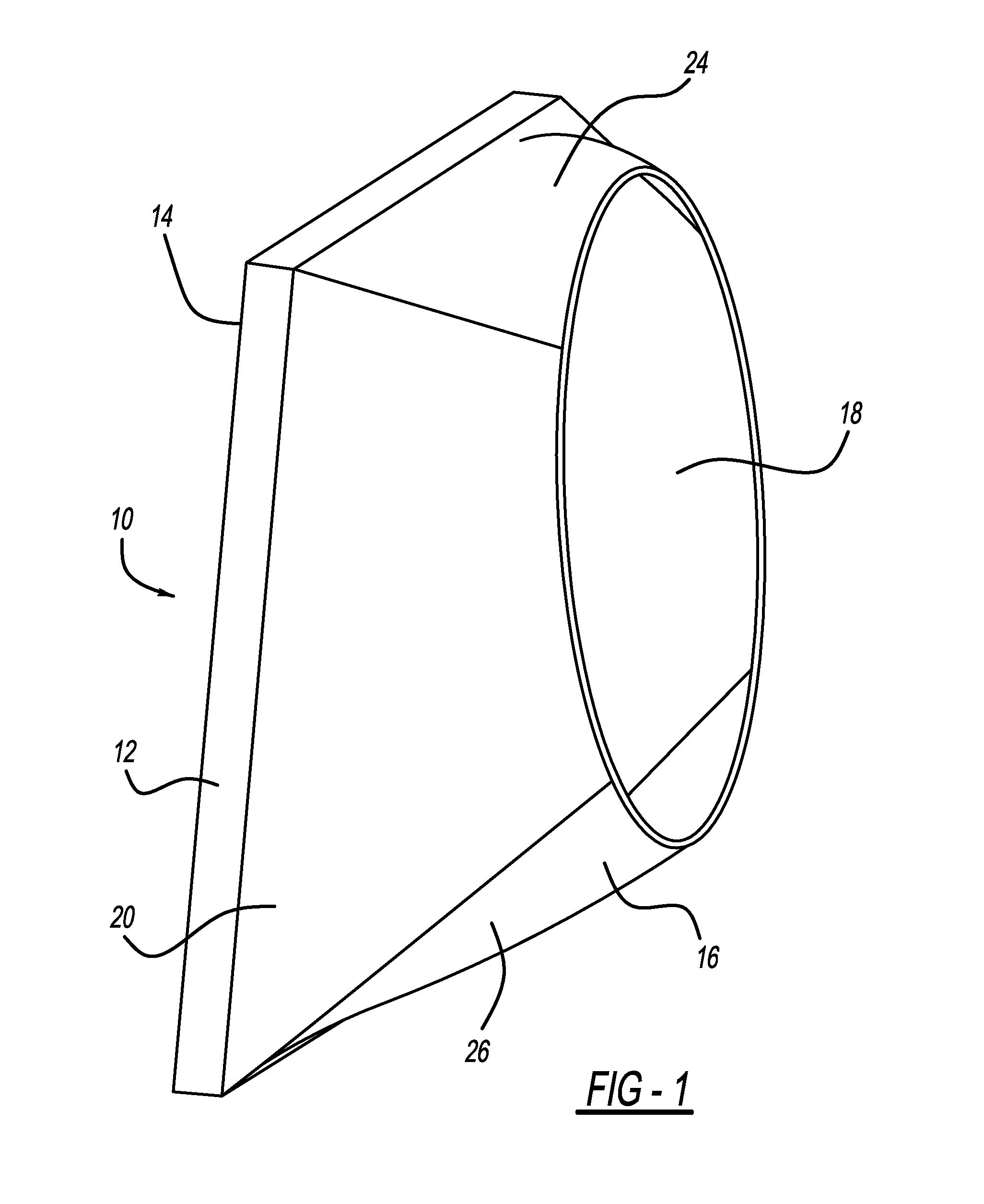
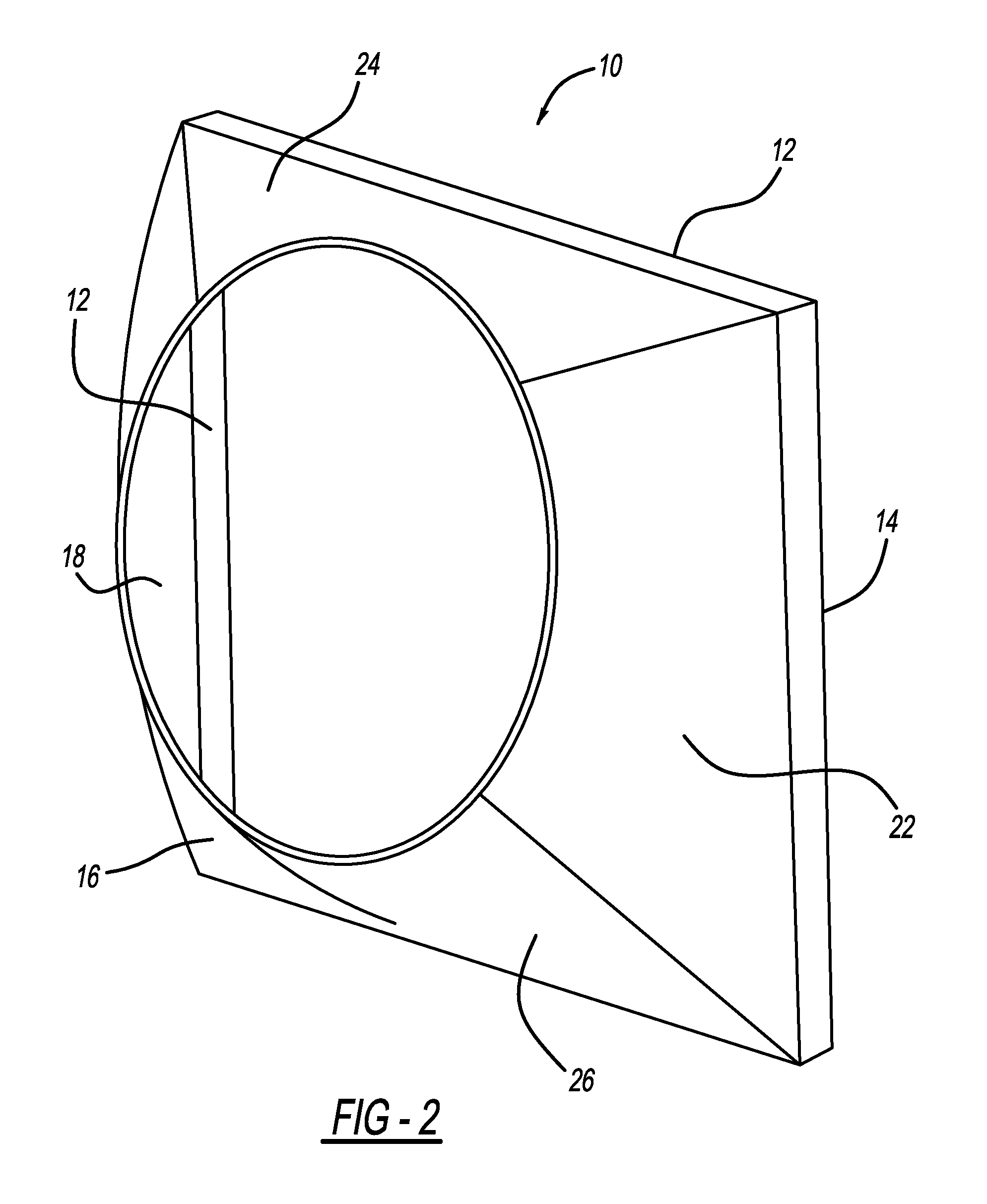
[0023]Referring to FIGS. 1 and 2, perspective side views of a convex fan shroud according to the disclosed inventive concept, generally illustrated as 10, are shown. The illustrated overall configuration of the convex fan shroud 10 is suggestive as alternative configurations, which may be, for example, longer, wider or taller, may be adopted as well while still fallin...


PUM

PropertyMeasurementUnit
air movementaaaaaaaaaa
air flow ratesaaaaaaaaaa
liquid capacityaaaaaaaaaa

Abstract

A convex fan shroud for use with an automotive engine cooling system having a fan and a fan-cooled, liquid-to-air radiator is disclosed. The convex fan shroud has an optimized shape that leads to high air flow rates through the radiator. The convex fan shroud includes a front frame that defines an air-intake opening, a convex top wall connected to the frame, a convex bottom wall connected to the frame, and a pair of opposed convex side walls connected to the frame and to the top and bottom walls. The interior surfaces of the walls are smooth. The convex walls define a barrel-shaped shroud body that includes a round engine-facing opening to accommodate the fan. In addition to generating a higher flow rate, the disclosed inventive concept for a smooth convex fan shroud is relatively low cost to produce and has a relatively high degree of rigidity.

Description

TECHNICAL FIELD[0001]The disclosed inventive concept relates generally to enhanced air cooling constructions for internal combustion engines. More particularly, the disclosed inventive concept is directed to a convex fan shroud having an optimum shape that leads to high air flow rates through the radiator and improved system efficiency without the need for additional engine input power.BACKGROUND OF THE INVENTION[0002]The conventional liquid-cooled internal combustion engine relies primarily on axial flow fans to draw cooling air from outside of the vehicle through the liquid-to-air heat exchanger or radiator for cooling. Various efforts have been made to improve cooling, including increasing the liquid capacity of the radiator, increasing the size or number of fan blades, and changing the pitch of the fan blades.[0003]Complicating the challenge of efficiently cooling the liquid-cooled internal combustion engine is the fact that engine undergoes air flow and temperature changes duri...

Claims


Application Information

Patent Timeline
Patent Type & Authority Patents(United States)
IPC IPC(8): F01P7/02F01P1/02F01P5/04F01P7/04F01P7/08F01P5/12
CPCF01P1/02F01P5/04F01P5/12F01P7/046F01P7/084F01P2025/66F01P5/06F04D29/547Y10T29/49229
Inventor MEHRAVARAN, MEISAMO'DONOHUE, GARRETT MICHAELTYLER, JIMSTEWART, LAMAR
Owner FORD GLOBAL TECH LLC
Features
  • R&D
  • Intellectual Property
  • Life Sciences
  • Materials
  • Tech Scout
  • Unparalleled Data Quality
  • Higher Quality Content
  • 60% Fewer Hallucinations
Learn More