Supercharge Your Innovation With Domain-Expert AI Agents!

Motor with variable magnet flux

a variable magnet flux and motor technology, applied in the field of motors, can solve the problems of increasing manufacturing costs, complicated structure of the rotor core, and increasing manufacturing costs

Active Publication Date: 2016-04-05
NEW MOTECH
View PDF15 Cites 6 Cited by
  • Summary
  • Abstract
  • Description
  • Claims
  • Application Information

AI Technical Summary

Benefits of technology

[0017]The variable magnetic flux motor according to the present invention is simple in structure, and can reduce manufacturing costs and cause a high performance enhancement because it is favorable to concentration of the amount of magnetic flux.

Problems solved by technology

Accordingly, the motor according to the prior art 2 has several problems in that the rotor core is complicated in structure and manufacturing costs are increased.
Particularly, the first magnet is a neodymium (Nd) magnet, and it is the factor in an increase of manufacturing costs.

Method used


Image

  • Motor with variable magnet flux
  • Motor with variable magnet flux
  • Motor with variable magnet flux

Examples


embodiment

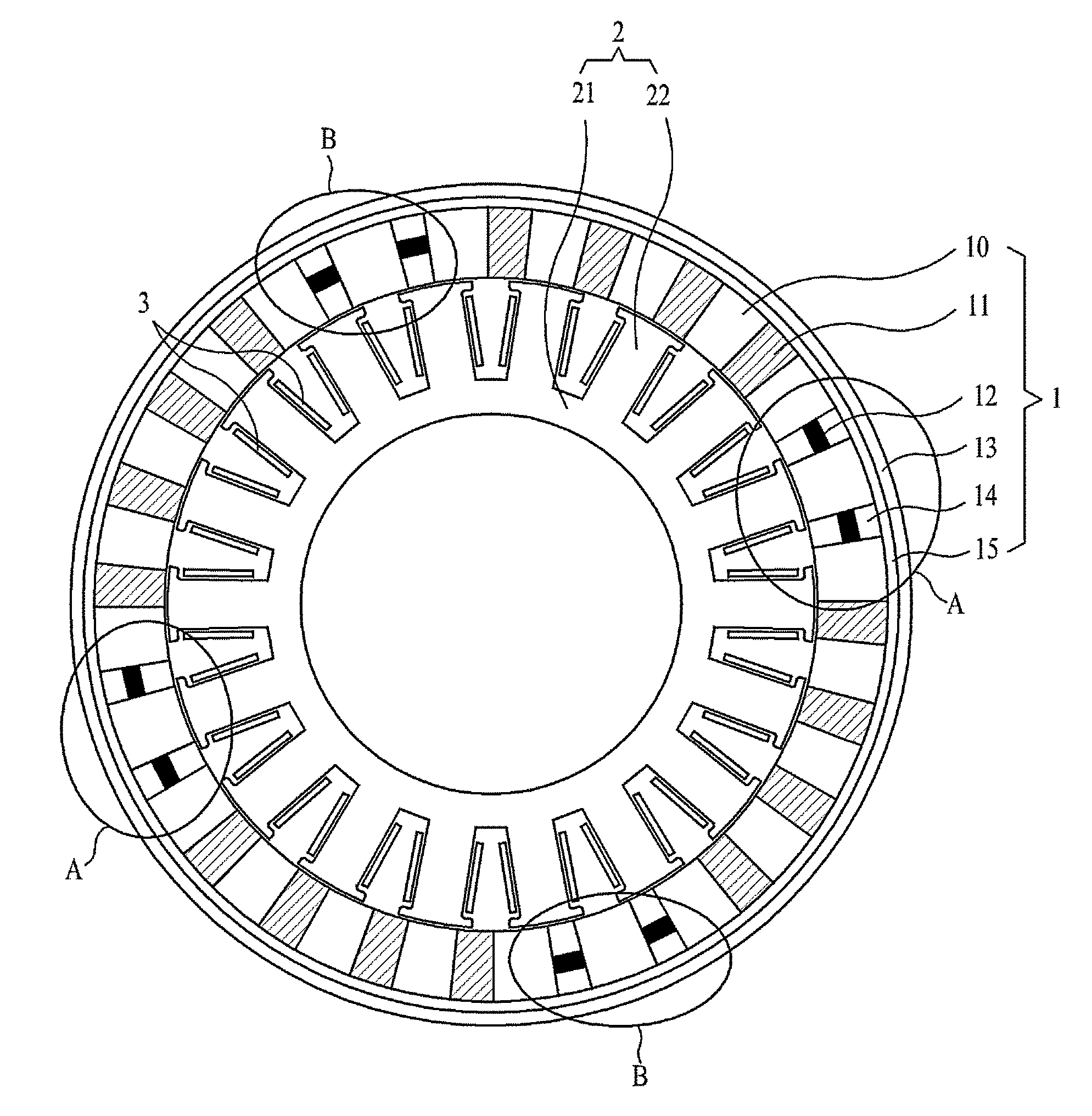
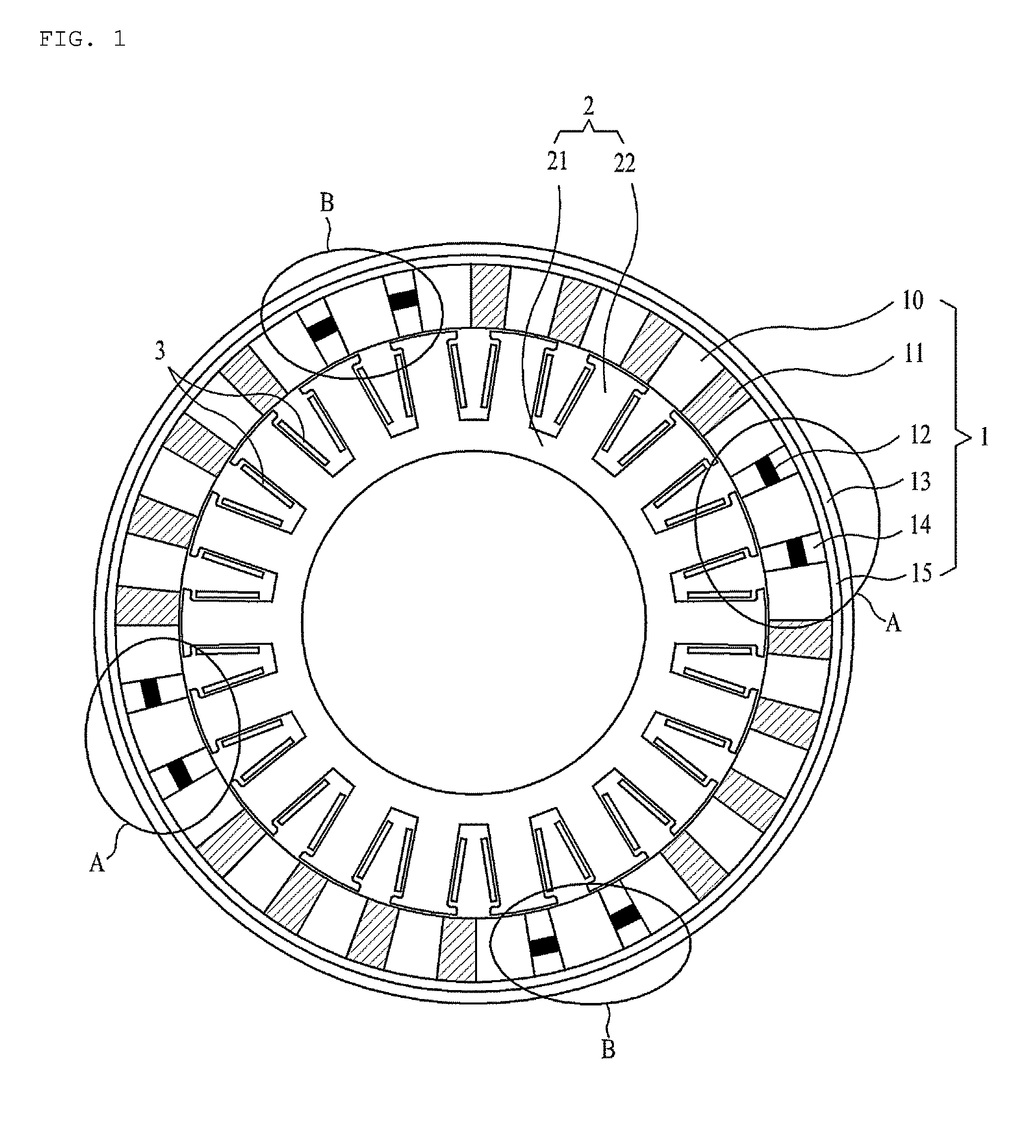
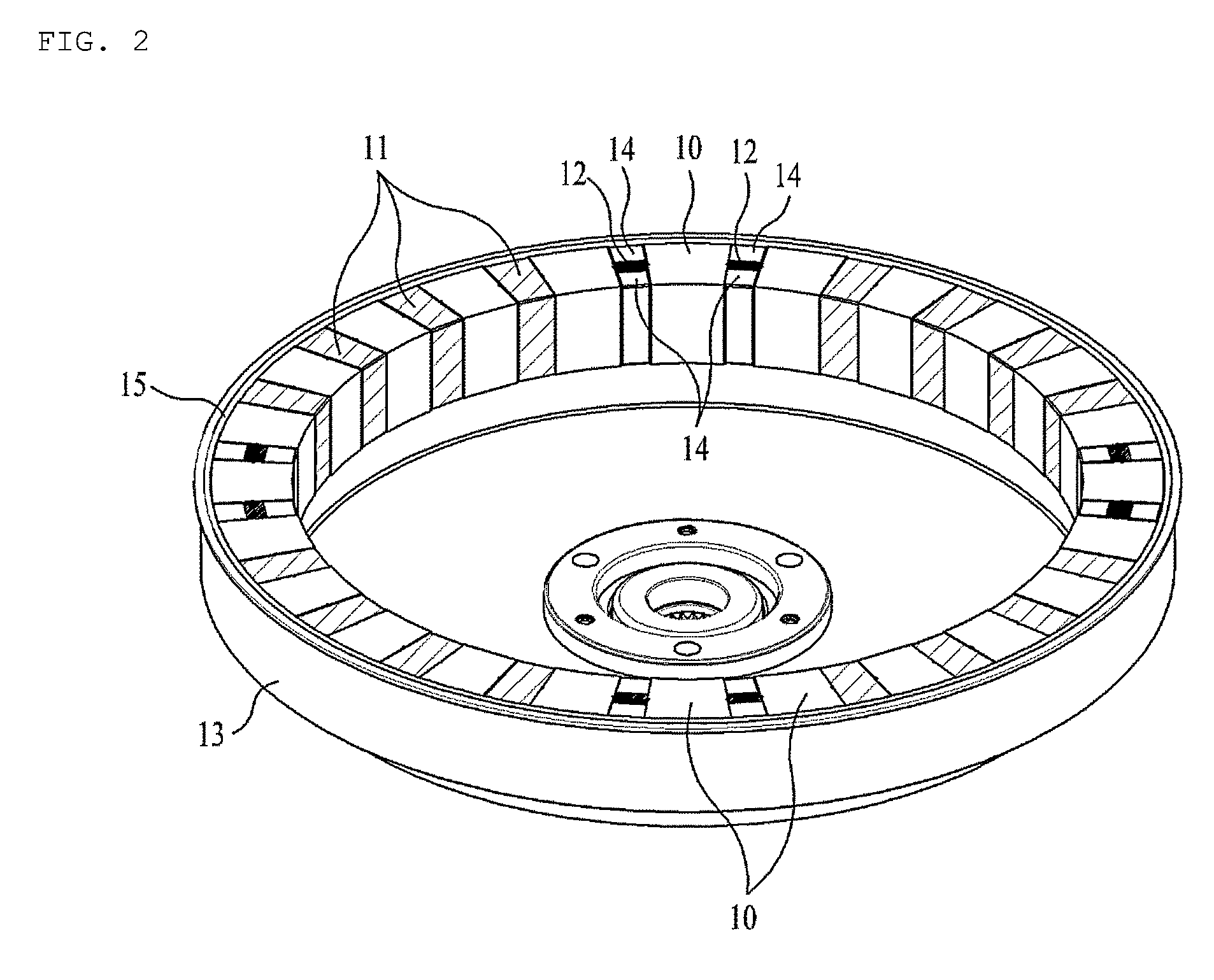
[0048]In order to analyze demagnetization characteristic of the variable magnetic flux motor according to the present invention, the finite element analysis (FEA) was applied. After the motor with 24 poles-18 slots was manufactured, the FEA was applied under various analyzing conditions.

[0049]First, under a no-load operation, a counter electromotive force at 45 rpm in full magnetization of the alnico magnets was measured, and after that, the counter electromotive force was measured after the motor was operated at 45 rpm in a state where the alnico magnets were demagnetized. The measurement results were illustrated in FIGS. 7 and 8. FIG. 7 illustrates the measurement result at the time of the full magnetization and FIG. 8 illustrates the measurement result at the time that the alnico magnets were demagnetized.

[0050]As shown in FIGS. 7 and 8, the counter electromotive force at the time of full magnetization and the counter electromotive force at the time of demagnetization were compar...


PUM


Abstract

Disclosed therein is a motor with a variable magnetic flux, which includes a rotor and a stator located inside the rotor. The rotor includes a rotor housing, a plurality of unit rotor cores and magnets which are attached to the inner wall surface of the rotor housing, and the unit rotor cores and the magnets are arranged in turn. The stator includes a stator core base and a plurality of teeth radially formed on the outer peripheral surface of the stator core base at equal intervals, and each of the teeth has ears formed at both sides of an end thereof.

Description

CROSS REFERENCE TO PRIOR APPLICATIONS[0001]This application claims priority under 35 U.S.C. §119 to Korean Patent Application No. 10-2012-0139158, filed on Dec. 3, 2012, which is hereby incorporated by reference in its entirety.BACKGROUND OF THE INVENTION[0002]1. Field of the Invention[0003]The present invention relates to a motor. More particularly, the present invention relates to a new structure of a motor, which can be operated at a variable speed by demagnetizing or magnetizing some of magnets applied to a rotor and can obtain high efficiency by concentrating an amount of magnetic flux.[0004]2. Background Art[0005]In general, in order to simultaneously obtain a variable speed operation and high efficiency of a motor, various structures and forms of motors have been proposed.[0006]Representatively, there are a variable flux memory motor (VFMM) (hereinafter, called “prior art 1”) and a motor disclosed in Japanese Patent Laid-open No. 2009-112454 (hereinafter, called “prior art 2”...

Claims


Application Information

Patent Timeline
Patent Type & Authority Patents(United States)
IPC IPC(8): H02K1/27H02K1/02
CPCH02K1/2786H02K1/02H02K1/2791H02K1/27
Inventor JANG, JEONG CHEOLSEO, JE HYUNGPARK, SOO HYUNJUNG, WOON PILCHO, HUGH JINLEE, SEUNG JAEKIM, BYUNG TAEKJANG, JIN SEOK
Owner NEW MOTECH
Features
  • R&D
  • Intellectual Property
  • Life Sciences
  • Materials
  • Tech Scout
  • Unparalleled Data Quality
  • Higher Quality Content
  • 60% Fewer Hallucinations
Learn More