Check patentability & draft patents in minutes with Patsnap Eureka AI!

Unit moving device and image forming apparatus

a unit moving and image forming technology, applied in the direction of electrographic process apparatus, instruments, gearing, etc., can solve the problems of degrading the quality of an image, the unit is not sufficiently pushed to a position, and the sheet is not correctly positioned, so as to achieve the effect of reliably pulling into the main body of the apparatus

Active Publication Date: 2016-04-12
CANON KK
View PDF9 Cites 4 Cited by
  • Summary
  • Abstract
  • Description
  • Claims
  • Application Information

AI Technical Summary

Benefits of technology

The solution reduces operational force requirements, simplifies the device structure, and ensures reliable and efficient mounting of units, improving work efficiency and reducing the risk of defective sheet feeding or image quality issues.

Problems solved by technology

However, sometimes the unit is not sufficiently pushed to a position that is reached when the unit is completely mounted in the main body of the apparatus.
In such a case in which the unit is not fully mounted in the main body of the apparatus, when the unit is, for example, a sheet feeding cassette, sheets are not correctly positioned.
Thus, situations such as an image being incorrectly formed on the sheet or defective feeding of the sheet (the sheet being fed in a tilted position or sheet jamming) can occur.
When the unit is a transfer unit or the like that transfers an image onto the sheet, quality of an image is degraded due to a transfer of the image onto an incorrect position on a transported sheet.
However, there is a problem with the above-described related-art unit moving device.
This makes the structure be complex, thereby increasing the size and cost of the apparatus.
In this case, the size and cost of the apparatus, which increase in the case of the apparatus using the motor, do not increase.
Although the operability of the sheet feeding cassette is described above, similar problems occur in a transfer portion that transfers toner images onto a sheet, or in a transfer unit or a fixing unit of which a fixing device fixing toner images to a sheet can be pulled from the main body of the apparatus.
This also increases the size and weight of the image forming portion.
For this reason, degradation of work efficiency also occurs in structures that pull these units as is the case with a structure that pulls the sheet feeding cassette.

Method used


Image

  • Unit moving device and image forming apparatus
  • Unit moving device and image forming apparatus
  • Unit moving device and image forming apparatus

Examples


first embodiment

[0045]First, a sheet feeding cassette and an image forming apparatus equipped with a unit moving device according to a first embodiment of the present invention will be described with reference to the drawings. FIG. 13 is a sectional view illustrating a sheet feeding device, and FIG. 14 is a sectional view of the image forming apparatus. Although FIG. 14 illustrates a general configuration of a full-color laser beam printer, the present invention is not limited to this, and is applicable to other image forming apparatuses such as a facsimile device and a copying machine.

[0046]Referring to FIG. 14, reference numeral 1 denotes a full-color laser beam printer (simply referred to as a printer hereinafter), reference numeral 1A denotes a main body of the printer serving as a main body of an image forming apparatus (a main body of the apparatus), reference numeral 1B denotes an image forming portion that forms an image on a sheet, and reference numeral 20 denotes a fixing portion. Referen...

second embodiment

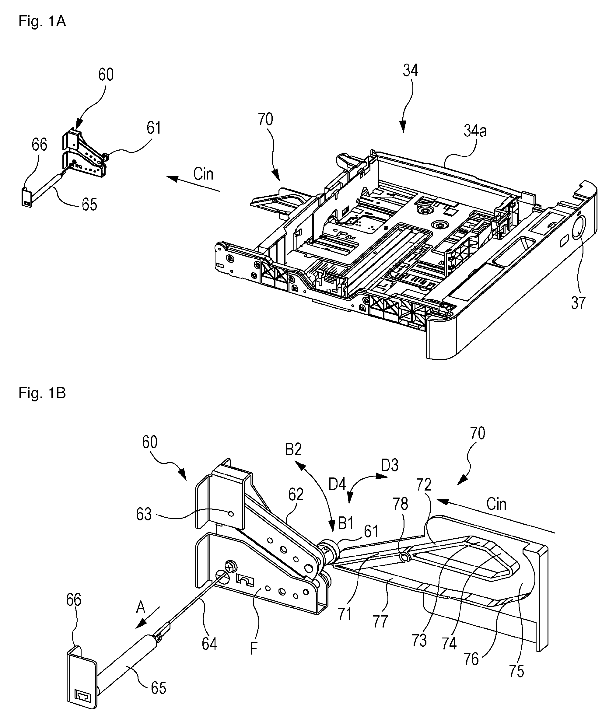
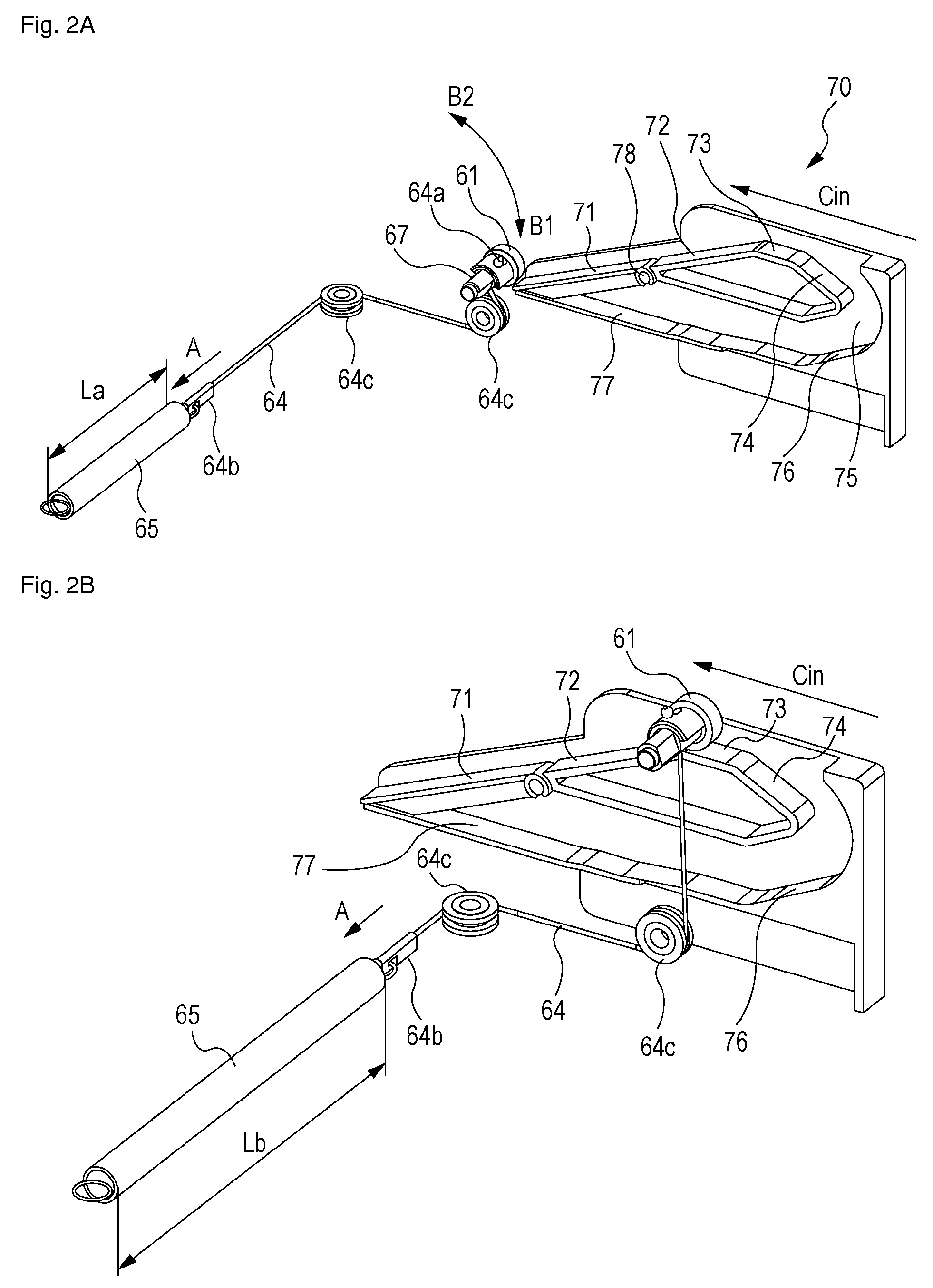
[0086]Next, a moving mechanism of the sheet feeding cassette 34 (the unit moving device) according to a second embodiment of the present invention will be described. In the second embodiment, the structure of the roller guiding portion 70 is different from that in the first embodiment. Also in the second embodiment, the accumulating operation of the tension spring 65 serving as the elastic member is different from that of the tension spring 65 in the first embodiment in mounting the sheet feeding cassette 34. Similar to the first embodiment, in the second embodiment, part of the elastic force accumulated in the tension spring 65 is used as a pulling force when the sheet feeding cassette 34 is mounted in the main body of the apparatus, and, after retaining of the sheet feeding cassette 34 at the normal position is released, the remaining elastic force acts as force used to push the sheet feeding cassette 34 toward the outer side of the main body of the apparatus.

[0087]As a structure ...

third embodiment

[0091]FIGS. 12A and 12B illustrate in detail a unit moving device according to a third embodiment of the present invention. In the third embodiment, the structure of the roller guiding portion 70 is different from that in the second embodiment. As illustrated in FIG. 12B, the third embodiment uses the same structure of components as that of the second embodiment. Also similar to the second embodiment, the guide paths E1, E2, and E3 of the roller 61 are provided corresponding to the distance by which the sheet feeding cassette 34 is pulled out. Compared to the second embodiment, in the third embodiment, the distances of the inclined surfaces of the guide paths E1, E2, and E3 are different from each other, that is, the inclinations of the guiding surfaces, which are formed by the flappers 71, 171, and 271, and the inclined guides 72, 172, and 272, are different from each other.

[0092]In the present embodiment, inclination of the guiding surface of the guide path E1 is decreased, thereb...


PUM


Abstract

A roller is rotatably provided in an arm that is swingable relative to a main body of an apparatus, and is connected to a tension spring using a wire of a roller shaft. A roller guide portion that guides the roller is provided in a sheet feeding cassette. The roller is guided along a guiding member of the roller guide portion in accordance with insertion of the sheet feeding cassette into the main body of the apparatus. When the roller is guided along the guiding member, an elastic force of the tension spring is accumulated. The sheet feeding cassette is pulled to a mounting position when the roller is guided along the guiding member. The sheet feeding cassette is pushed out also when the roller is guided along the guiding member.

Description

TECHNICAL FIELD[0001]The present invention relates to a unit moving device that moves a unit relative to a main body of an image forming apparatus that is equipped with the unit such that the unit can be pulled out of the main body of the image forming apparatus. The present invention also relates to an image forming apparatus equipped with the unit moving device.BACKGROUND ART[0002]Today, image forming apparatuses that form images on sheets such as printers, facsimile devices, and copying machines are equipped with units that are removably mounted therein. These units can be detached by being slid relative to the main bodies of the image forming apparatuses (hereinafter referred to as the main bodies of the apparatuses). Such units include, for example, sheet feeding units that contain sheets, sheet feeding devices that feed sheets from sheet feeding cassettes, and image forming portions (transfer unit, fixing unit, and the like) that form images on sheets.[0003]After such a unit i...

Claims


Application Information

Patent Timeline
Patent Type & Authority Patents(United States)
IPC IPC(8): G03G21/16G03G15/00F16H21/44
CPCG03G15/6505F16H21/44G03G21/16G03G2215/00383G03G2215/1695Y10T74/18896G03G15/00
Inventor HIURA, HIROSHIHAYAYUMI, FUMIHIKOUBAYASHI, SHINSUKE
Owner CANON KK
Features
  • R&D
  • Intellectual Property
  • Life Sciences
  • Materials
  • Tech Scout
  • Unparalleled Data Quality
  • Higher Quality Content
  • 60% Fewer Hallucinations
Learn More