Supercharge Your Innovation With Domain-Expert AI Agents!

Adjustable camshaft drive

a camshaft drive and camshaft technology, applied in the direction of valve drives, valve details, valve arrangements, etc., can solve the problems of small play or slackness between, and achieve the effect of cost-effective manufacturing and simple construction

Inactive Publication Date: 2016-04-19
VOLKSWAGEN AG
View PDF23 Cites 1 Cited by
  • Summary
  • Abstract
  • Description
  • Claims
  • Application Information

AI Technical Summary

Benefits of technology

[0008]It is accordingly an object of the invention to provide a camshaft drive which overcomes disadvantages of the heretofore-known camshaft drives of this general type. In particular, it is an object of the invention to provide a camshaft drive with a shaft-in-shaft system, wherein the camshaft drive is simple in construction and cost-efficient to manufacture. Furthermore, there should only be a small play or slackness between the drive element and the shaft-in-shaft system.
[0018]The camshaft drive according to the invention has the advantage that, with the drive shaft, a direct connection is established both to the outer shaft transmission element as well as to the stator. Thus, a play or clearance caused by any intermediate elements as well as additional production costs and assembly costs for the manufacturing and the installation of intermediate elements are avoided.
[0019]According to another feature of the invention, the outer shaft transmission element is an outer shaft gearwheel; the drive element is a drive gearwheel; the outer shaft gearwheel meshes with the drive gearwheel; and the stator has an outer toothing which also meshes with the drive gearwheel. Thus, in a practical embodiment of the camshaft drive according to the invention, the outer shaft transmission element is an outer shaft gearwheel, and the drive element is a drive gearwheel, wherein the outer shaft gearwheel meshes with the drive gearwheel. Furthermore the stator has an outer toothing, which likewise meshes with the drive gearwheel. In addition to the above-mentioned advantage of a direct transmission of the drive torque from the drive element to the outer shaft gearwheel and the stator, gearwheel connections have the advantage that they are very durable and low-maintenance. Further, gearwheel connections have a relatively high efficiency when compared to other transmission elements.
[0024]According to another feature of the invention, the stator is formed of several individual elements. Thus, the stator of a camshaft drive according to the invention is preferably formed from several individual elements, such as the stator drive element, the stator housing, and the stator cover, which are furthermore preferably connected to one another through the use of a screwed connection or by a material bond. As a result, a relatively complex geometry with a low total weight can be manufactured while having at the same time the lowest possible production expenditure.

Problems solved by technology

Furthermore, there should only be a small play or slackness between the drive element and the shaft-in-shaft system.

Method used


Image

  • Adjustable camshaft drive
  • Adjustable camshaft drive

Examples


Embodiment Construction

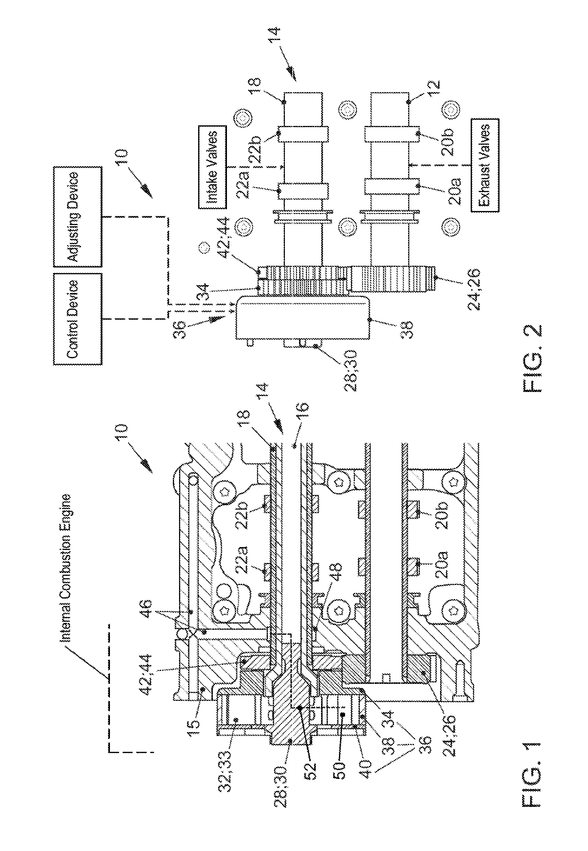
[0032]Referring now to the figures of the drawings in detail, there is shown, in an internal combustion engine, an embodiment of a camshaft drive 10 according to the invention with a drive shaft 12 embodied as a hollow shaft as well as a shaft-in-shaft system 14 disposed parallel to the drive shaft 12, which are mounted in a housing 15. The shaft-in-shaft system 14 includes an inner shaft 16, which is also embodied as a hollow shaft, as well as a coaxially disposed outer shaft 18, which surrounds the inner shaft 16.

[0033]Two exhaust cams 20a, 20b are disposed on the drive shaft 12 for co-rotation, i.e. fixed against relative rotation with respect to the drive shaft 12. Further, a drive gearwheel 26 is disposed as a drive element 24 on the drive shaft in a manner that is fixed against relative rotation.

[0034]A first intake cam 22a is disposed on the inner shaft 16 in a manner fixed against relative rotation. As can be seen in FIG. 1, the inner shaft 16 protrudes on the left side from...


PUM


Abstract

A camshaft drive includes a drive shaft having at least one cam for actuating a valve of an internal combustion engine. A shaft-in-shaft system is disposed parallel to the drive shaft and has an inner shaft and an outer shaft each having at least one cam for actuating a valve. The outer shaft is connected to an outer shaft transmission element in a manner fixed against relative rotation. A hydraulic transmission device includes a stator, a rotor, and an intermediate member. The inner shaft is coupled to the drive shaft via the hydraulic transmission device which is operatively connected to an adjusting device and to a control device for setting a desired phase angle between the inner shaft and the outer shaft. A drive element is coupled to the drive shaft. The drive element is directly coupled both to the outer shaft transmission element and to the stator.

Description

CROSS-REFERENCE TO RELATED APPLICATIONS[0001]This application is a continuation, under 35 U.S.C. §120, of copending International Application No. PCT / EP2012 / 074814, filed Dec. 7, 2012, which designated the United States; this application also claims the priority, under 35 U.S.C. §119, of German Patent Application No. DE 10 2011 120 815.5, filed Dec. 10, 2011; the prior applications are herewith incorporated by reference in their entirety.BACKGROUND OF THE INVENTIONField of the Invention[0002]The invention relates to an adjustable camshaft drive.[0003]German Patent Application No. DE 43 02 561 A1 discloses an adjustable valve controller for an internal combustion engine having two camshafts. In the case of this valve controller, the relative position of a first camshaft with respect to a second camshaft can be changed by an axial displacement of an actuating piston with a helical or spiral toothing via an oil pressure control device from a first position to a second position.[0004]Eu...

Claims


Application Information

Patent Timeline
Patent Type & Authority Patents(United States)
IPC IPC(8): F01L1/34F01L1/02F01L1/344F01L1/047F01L1/053
CPCF01L1/344F01L1/026F01L1/3442F01L2001/0473F01L2001/0537
Inventor ELFERS, UWE
Owner VOLKSWAGEN AG
Features
  • R&D
  • Intellectual Property
  • Life Sciences
  • Materials
  • Tech Scout
  • Unparalleled Data Quality
  • Higher Quality Content
  • 60% Fewer Hallucinations
Learn More