Check patentability & draft patents in minutes with Patsnap Eureka AI!

Optical recording and playback apparatus

a technology which is applied in the field of optical recording and playback apparatus, can solve the problems of optical tape deformation, optical tape vibration, optical tape vibration, etc., and achieve the effect of high quality

Active Publication Date: 2016-05-03
PANASONIC INTELLECTUAL PROPERTY MANAGEMENT CO LTD
View PDF16 Cites 0 Cited by
  • Summary
  • Abstract
  • Description
  • Claims
  • Application Information

AI Technical Summary

Benefits of technology

This configuration enhances the recording and playback quality on optical tapes by maintaining precise tracking and focus control, reducing tracking errors and signal degradation, even under conditions of high-frequency vibrations and aging.

Problems solved by technology

In a case where a recording position irradiated with a light beam on the optical tape vibrates at a higher frequency in the optical recording and playback apparatus in which data is recorded by irradiation of the light beam, when an actuator which drives an objective lens or the like that is one of optical systems controlling the irradiation of the light beam lacks thrust, the irradiation of the light beam cannot follow the vibration of the optical tape, and the optical tape cannot stably be irradiated with the light beam.
A tracking mirror is used as the optical system against the high-frequency vibration of the optical tape, and driven by the actuator, which results occasionally in a problem in that a spot in which an image is formed on the optical tape degrades or that an offset of a tracking error signal increases to lead to instability in the tracking control.
Additionally, the signal quality of the recording or playback degrades occasionally due to long continuous running or the aging of the optical tape.

Method used


Image

  • Optical recording and playback apparatus
  • Optical recording and playback apparatus
  • Optical recording and playback apparatus

Examples


first exemplary embodiment

[0040][1. Configuration of Optical Tape]

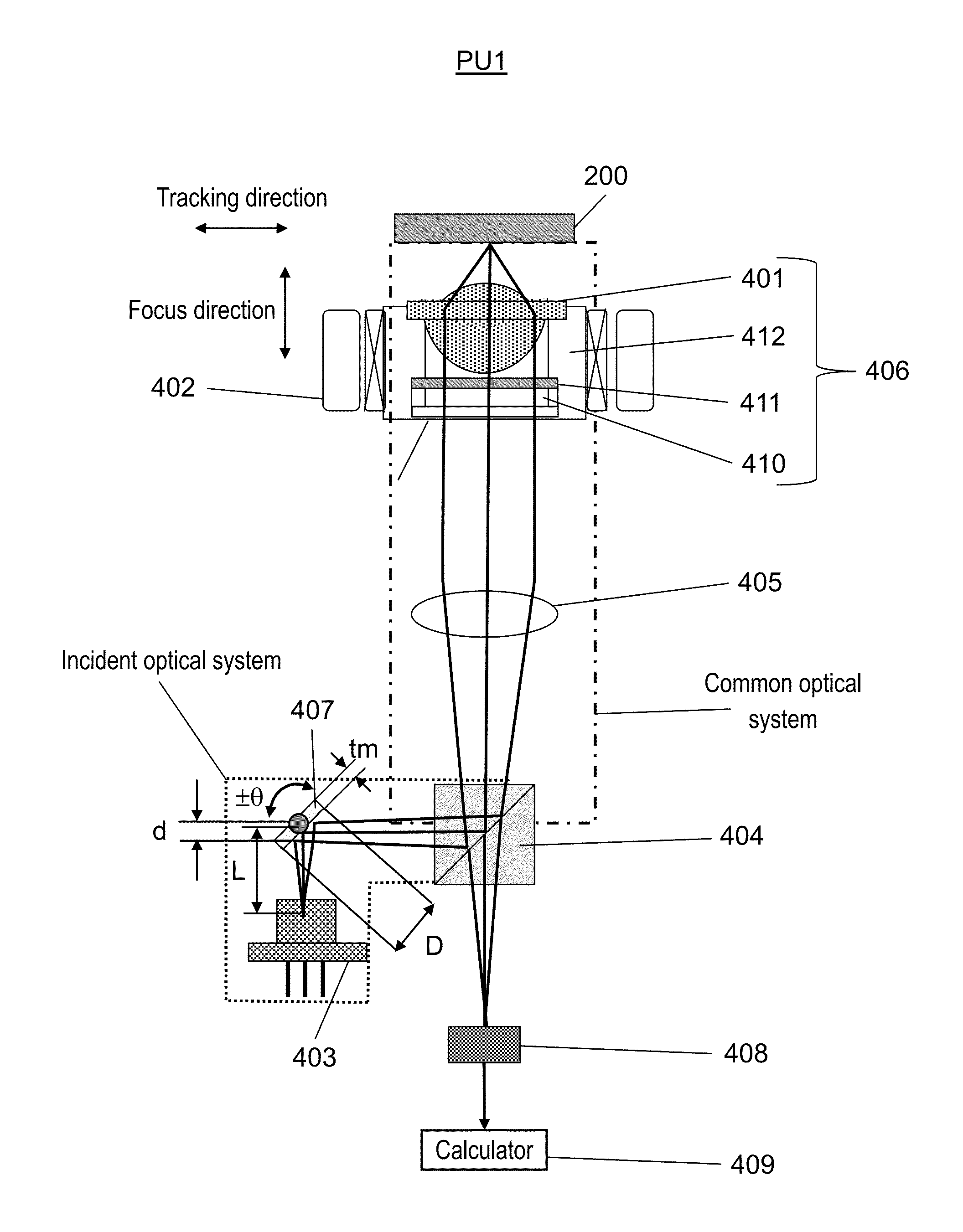
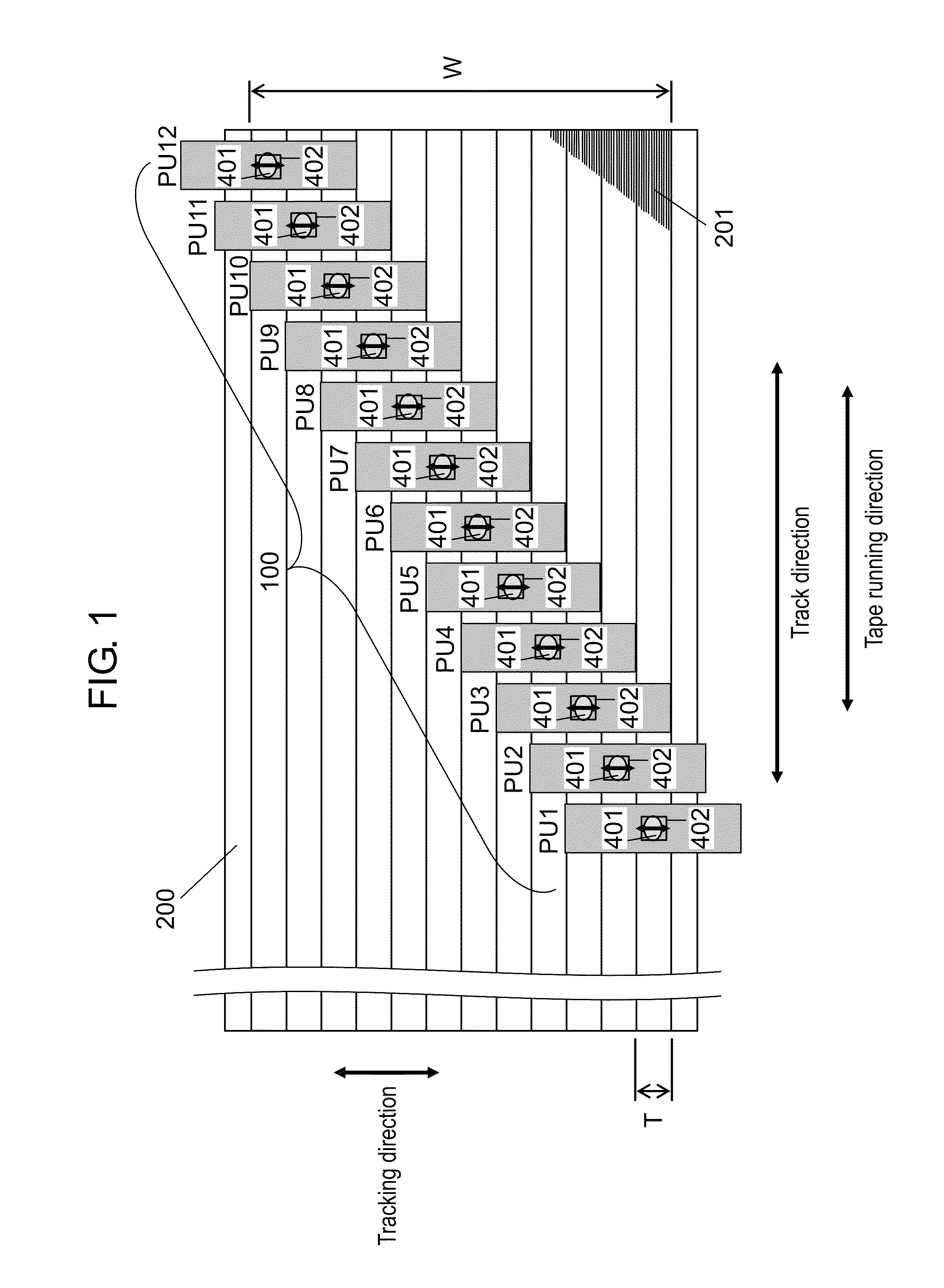
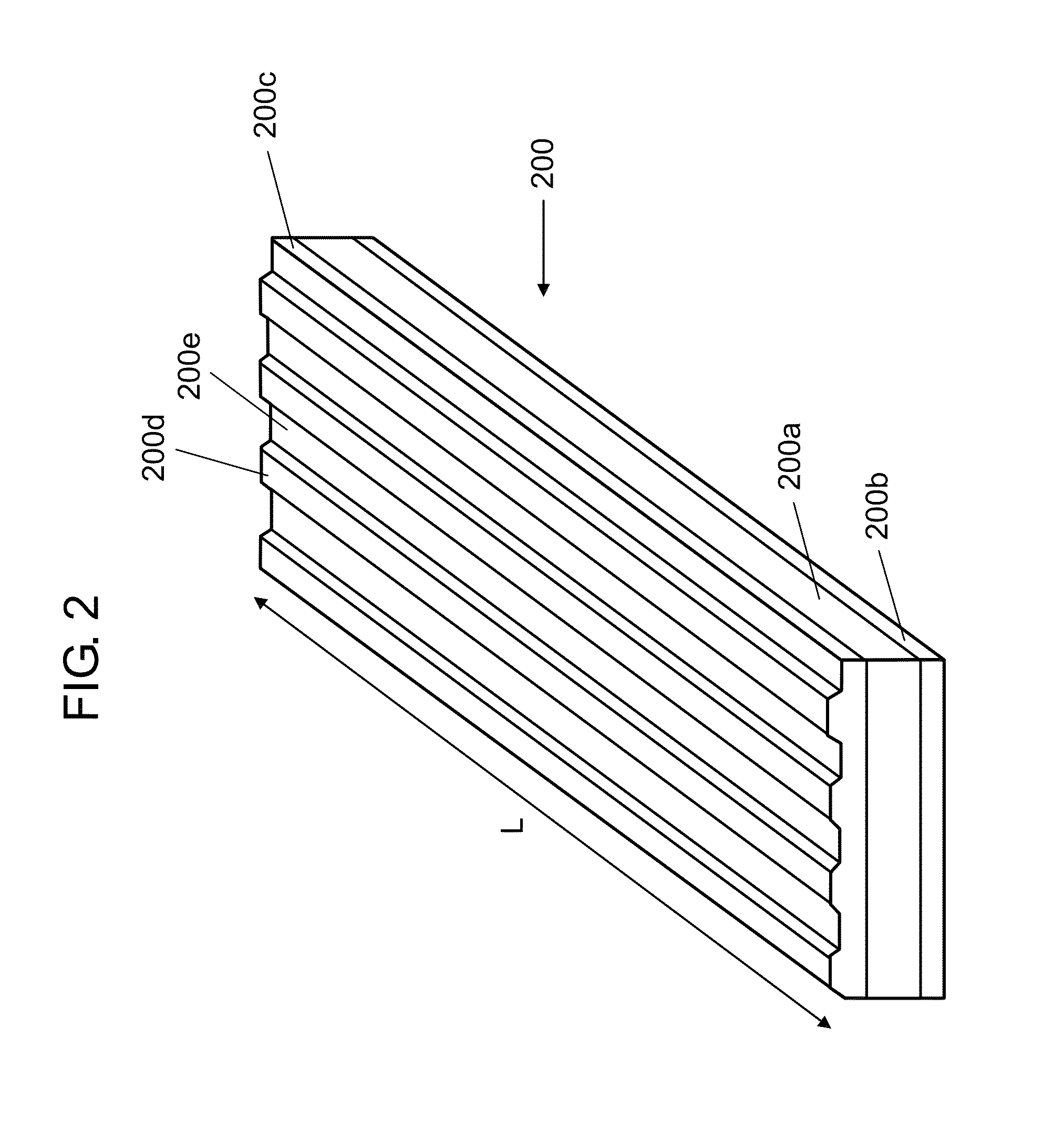
[0041]In the present exemplary embodiment, an optical tape is used as an optical recording medium. FIG. 1 is a view illustrating a relationship between pickup 100 of an optical recording and playback apparatus and optical tape 200 in which information is recorded according to the present exemplary embodiment.

[0042]The optical recording and playback apparatus of the present exemplary embodiment includes pickup 100. The optical recording and playback apparatus records data in optical tape 200, and plays back the data from optical tape 200.

[0043]In FIG. 1, pickup 100 includes 12 pickup units PU1 to PU12. 12 pickup units PU1 to PU12 are arrayed in a direction substantially perpendicular to a track direction that is a tape running direction of optical tape 200. The reason pickup 100 includes a plurality of pickup units is that a data transfer rate to optical tape 200 is enhanced. Pickup units PU1 to PU12 irradiate corresponding recording regions of...

second exemplary embodiment

[0133]In the first exemplary embodiment, the optical recording and playback apparatus is provided with the tracking mirror, and the pickup deals with the high-frequency LTM. The conditions and configurations, which should solve the problems generated during the operation of the tracking mirror in the optical recording and playback apparatus of the first exemplary embodiment, are also described in the first exemplary embodiment. Only one axis in which the light beam is polarized in the tracking direction is operated in the tracking mirror of the first exemplary embodiment. In a tracking mirror according to a second exemplary embodiment, the tracking mirror can be operated in a two-axis manner, in other words, not only the tracking direction but also the track direction.

[0134]Generally the optical recording and playback apparatus is aimed at applications of continuously recording and storing the large-capacity data of the data center and the like or applications of backing up the data...


PUM

PropertyMeasurementUnit
thicknessaaaaaaaaaa
sizeaaaaaaaaaa
widthaaaaaaaaaa

Abstract

An optical recording and playback apparatus includes: a light source configured to emit a light beam; a tracking mirror configured to change a direction of the light beam; a collimator configured to form the light beam into a parallel light beam; an objective lens configured to collect the parallel light beam to the optical tape; a lens actuator configured to adjust a position of the objective lens in a focus direction of the optical tape and a position of the objective lens in a tracking direction of the optical tape; a polarization hologram plate configured to separate a reflected light beam of the light beam; a photodetector receiving elements configured to receive the plurality of light fluxes; and a control circuit configured to control the lens actuator and the tracking mirror. The tracking mirror is disposed near the light source, and movable in the tracking direction.

Description

BACKGROUND OF THE INVENTION[0001]1. Field of the Invention[0002]The present disclosure relates to an optical recording and playback apparatus that records and plays back information in and from an optical recording medium such as an optical tape.[0003]2. Description of the Related Art[0004]An optical tape apparatus in which the recording or playback is simultaneously performed on an optical tape medium with a plurality of optical pickups by making use of an optical high-density recording technology has been proposed as a recording and playback apparatus suitable for storage application. For example, PTL 1 discloses an example of the optical tape apparatus.[0005]Further, in an optical recording and playback apparatus, it is necessary to properly perform focus control and tracking control during recording and playback operations. Particularly, compared with the focus control, higher accuracy is required in the tracking control of the optical tape apparatus in which the optical tape is...

Claims


Application Information

Patent Timeline
Patent Type & Authority Patents(United States)
IPC IPC(8): G11B7/09G11B7/003G11B7/24009G11B7/1392G11B7/1353G11B7/13G11B7/00G11B7/1362
CPCG11B7/13927G11B7/003G11B7/0901G11B7/0903G11B7/094G11B7/24009G11B7/13G11B7/1353G11B7/1362G11B2007/0003G11B7/131G11B7/1381G11B7/14
Inventor SAITOH, YOHICHIHAYASHI, HIDEKIASADA, JUN-ICHI
Owner PANASONIC INTELLECTUAL PROPERTY MANAGEMENT CO LTD
Features
  • R&D
  • Intellectual Property
  • Life Sciences
  • Materials
  • Tech Scout
  • Unparalleled Data Quality
  • Higher Quality Content
  • 60% Fewer Hallucinations
Learn More