Unlock instant, AI-driven research and patent intelligence for your innovation.

Image processing device, projector, and image processing method

a technology of image processing and projector, applied in the direction of printers, instruments, camera focusing arrangement, etc., can solve the problems of insufficient focus adjustment, insufficient accuracy of focus adjustment, and difficult accurate adjustment, so as to suppress the influence of direction and improve the accuracy of focus adjustment

Active Publication Date: 2016-07-05
SEIKO EPSON CORP
View PDF6 Cites 0 Cited by
  • Summary
  • Abstract
  • Description
  • Claims
  • Application Information

AI Technical Summary

Benefits of technology

The solution enhances the accuracy of focus adjustment by adapting the adjusting image to the projection direction, ensuring precise alignment and improving the overall focus adjustment process.

Problems solved by technology

In the case of performing the focus adjustment described above, the focus adjustment becomes insufficient in some cases depending on the projection state of the projector at the beginning of the focus adjustment such as the relative positional relationship between the projector and the projection surface, the defocus condition before the focus adjustment, the focus position of the focusing lens before the focus adjustment, and the performance of the image-taking camera.
In such cases as described above, since the difference in grayscale between the white line portion and the black line portion of the taken projection image before the adjustment is small from the beginning, there arises a problem that even if the focus position of the focusing lens is varied, the variation is also small to make the accurate adjustment difficult, which might cause the insufficient focus adjustment in some cases.

Method used


Image

  • Image processing device, projector, and image processing method
  • Image processing device, projector, and image processing method
  • Image processing device, projector, and image processing method

Examples


first embodiment

[0051]Firstly, a configuration of a projector will be explained.

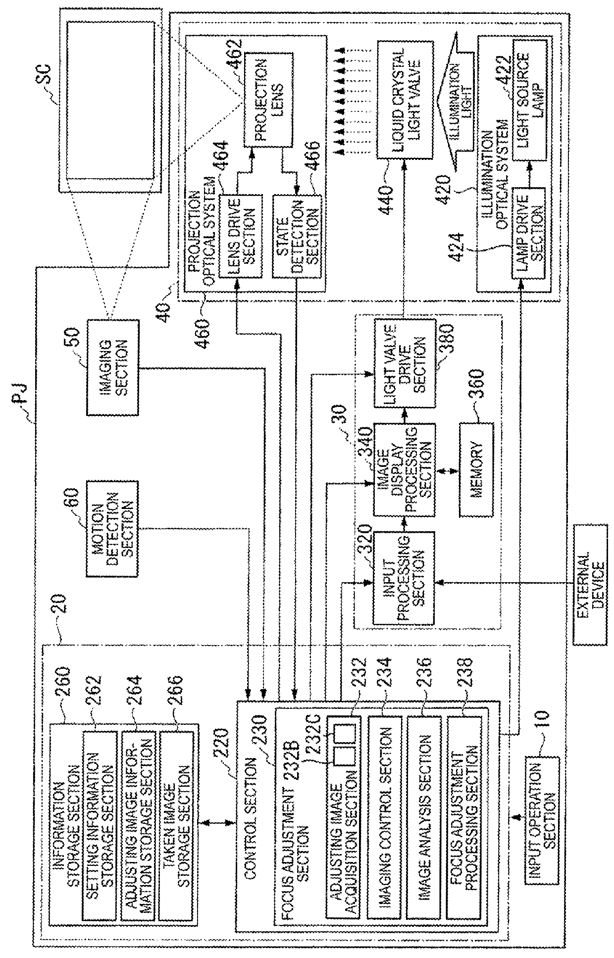
[0052]FIG. 1 is a block diagram schematically showing the configuration of the projector. The projector PJ is provided with an input operation section 10, a control circuit 20, an image processing operation circuit 30, an image projection optical system 40, an imaging section 50, and a motion detection section 60.

[0053]The input operation section 10 is composed of, for example, a remote controller, and buttons and keys provided to the projector PJ, wherein the buttons and the keys are not shown in the drawing. The input operation section 10 outputs instruction information corresponding to the operation by the user to the control circuit 20. For example, the instruction information of starting or stopping a focus adjustment process described later is output from the user to the control circuit 20.

[0054]The image projection optical system 40 generates image light representing an image, and then images the image light on a...

second embodiment

[0120]The second embodiment is different from the first embodiment in the point that the tilt angle of the projector PJ is detected based on the position of a bright point projected from the laser emission device on the screen SC. Hereinafter, only the difference from the first embodiment will be explained.

[0121]FIG. 20 shows a diagram for explaining a method of detecting the tilt of the screen with respect to the projector. In FIG. 20, the laser beam is projected from the laser emission device 500 on the screen SC to thereby project the bright point 510 due to the laser beam on the screen SC. The imaging section 50 images the bright point 510 projected on the screen SC a plurality of times, and then detects the information regarding the direction in which the adjusting image is projected on the screen SC based on the movement of the bright point 510 thus imaged.

[0122]Further, the image analysis section 236 performs the analysis of the taken image. In the case in which the bright po...


PUM


Abstract

An image processing device is capable of suppressing the influence of the direction in which the image is projected on the projection surface to thereby improve the accuracy of the focus adjustment. The image processing device includes a detection section adapted to detect information regarding a direction in which an adjusting image for adjusting focus of an image to be projected on a projection surface is projected on the projection surface, and an adjusting image acquisition section adapted to obtain the adjusting image different in accordance with the information regarding the direction detected by the detection section.

Description

[0001]The entire disclosure of Japanese Patent Application No. 2012-199332, filed Sep. 11, 2012, is expressly incorporated by reference herein.BACKGROUND[0002]1. Technical Field[0003]The present invention relates to an image processing device, a projector, and an image processing method.[0004]2. Related Art[0005]In the case of projecting an image on a projection surface such as a screen to thereby display the image using a projector, there are usually performed a focus adjustment for adjusting the shift of the focus of the image (hereinafter also referred to as a “projection image”) projected on the projection surface, a keystone correction for correcting the distortion (hereinafter also referred to as a “keystone distortion”) of the image range of the projection image, and so on.[0006]As described in, for example, JP-A-2010-32842, the focus adjustment is performed by projecting a patterned image having a stripe shape with white lines and black lines arranged alternately, and varyin...

Claims


Application Information

Patent Timeline
Patent Type & Authority Patents(United States)
IPC IPC(8): G03B21/14G03B21/53H04N9/31G09G3/00G03B3/00
CPCG03B21/147G03B21/53H04N9/317H04N9/3185G09G3/001
Inventor NAKASHIN, YOSHITAKA
Owner SEIKO EPSON CORP