Apparatus and method of ink-jet recording and non-transitory computer-readable storage medium
a technology of inkjet recording and computer-readable storage medium, which is applied in the direction of printing, other printing apparatus, etc., can solve the problems of ink ejection failure, increase in the temperature of the recording head, and increase so as to prevent the excessive rise in the temperature of the ejection port and reduce the throughput
- Summary
- Abstract
- Description
- Claims
- Application Information
AI Technical Summary
Benefits of technology
Problems solved by technology
Method used
Image


Examples
first embodiment
[0041]the present invention will be described in detail hereinbelow with reference to the drawings.
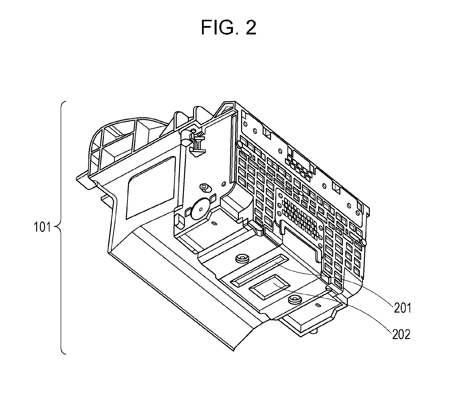
[0042]FIG. 1 is a perspective view of part of the internal configuration of an ink-jet recording apparatus 1000 according to the first embodiment.
[0043]An interchangeable head cartridge 100 includes a recording head 101 (see FIG. 2) for ejecting ink, described later, and an ink tank for supplying ink to the recording head 101. The head cartridge 100 is detachably held by a carriage 102. The carriage 102 and the head cartridge 100 are moved in forward and backward directions along an X-direction (a scanning direction) by driving a carriage motor 103. At that time, a driving force from the carriage motor 103 is transmitted to the carriage 102 through a carriage belt 104. During the forward and backward scanning operations of the carriage 102, the recording head 101 ejects ink according to recording data, so that recording on a recording medium is performed (a recording operation). The re...
second embodiment
[0124]In a second embodiment, the tendency of an excessive rise in the temperature of the ejection ports is determined from the size of an image to be recorded.
[0125]The same as that of the first embodiment will be omitted.
[0126]In this embodiment, the dimension of an image recorded in a unit area in the X-direction is calculated on the basis of the recording data, and the scanning area of the recording head 101 is changed depending on the size.
[0127]FIG. 16 is a schematic diagram illustrating the scanning area of the recording head 101.
[0128]An image with a dimension of a distance Dd1 in the X-direction is recorded in a unit area 80c on the recording medium 3. An image with a dimension of a distance Dd2 (Dd2>Dd1) in the X-direction is recorded in a unit area 80d. Two images each having the dimension of the distance Dd1 in the X-direction are recorded in a unit area 80e. The distance between the upstream end of one of the two images recorded in the unit area 80e in the X-direction a...
PUM
 Abstract
Description
Claims
Application Information
 - R&D
- Intellectual Property
- Life Sciences
- Materials
- Tech Scout
- Unparalleled Data Quality
- Higher Quality Content
- 60% Fewer Hallucinations
Browse by: Latest US Patents, China's latest patents, Technical Efficacy Thesaurus, Application Domain, Technology Topic, Popular Technical Reports.
© 2025 PatSnap. All rights reserved.Legal|Privacy policy|Modern Slavery Act Transparency Statement|Sitemap|About US| Contact US: help@patsnap.com