Check patentability & draft patents in minutes with Patsnap Eureka AI!

Toxic gas condensation and retreatment system

a technology of gas condensation and retreatment system, which is applied in the direction of separation process, dispersed particle separation, chemistry apparatus and processes, etc., can solve the problems of 5,000 deaths a year, relatively small part of combustion gas is undesirable, noxious or toxic, and catalytic converters also have shortcomings and limitations

Inactive Publication Date: 2016-09-06
ALMALOWI SAEED J
View PDF13 Cites 0 Cited by
  • Summary
  • Abstract
  • Description
  • Claims
  • Application Information

AI Technical Summary

Benefits of technology

The system effectively reduces and eliminates toxic gases by condensing and dissolving them in cold air vapor, recirculating them for further treatment, and agglomerating in a post-treatment tank, improving efficiency and durability while reducing emissions and fuel consumption.

Problems solved by technology

According to another study from the same institution, traffic fumes alone cause the death of 5,000 people every year in the United Kingdom.
Additionally, a relatively small part of combustion gas is undesirable noxious or toxic substances, such as carbon monoxide from incomplete combustion, hydrocarbons from unburnt fuel (CxHy), nitrogen oxides (NOx) from excessive combustion temperatures, ozone (O3) and particulate matter (mostly soot).
Due to their inability to control nitrogen oxides, two-way catalytic converters are gradually superseded by three-way catalytic converters.
Although proven to be reliable and effective in reducing noxious tailpipe emissions, catalytic converters also have some shortcomings and limitations.
For example, an engine equipped with a three-way catalytic converter must run at stoichiometric point, therefore increasing the consumption of fuel and adding approximately 10% more carbon dioxide emissions from the engine.
Gas concentrations that exceed or are below the limits will greatly reduce the efficiency and the life of a catalytic converter and it is very expensive to replace one.
The durability of a catalytic converter is also affected by thermal degradation and poisoning of the catalytic metals by impurities such as lead and sulfur in fuels and zinc, phosphorous and magnesium from lubricating oil additives.
Furthermore, unwanted reactions such as the formation of odoriferous hydrogen sulfide and ammonia can occur in three-way catalytic converters.
However, the continuing prevalence of catalytic converters in motor vehicles in the market may infer that such efforts have not accomplished the desired success.

Method used


Image

  • Toxic gas condensation and retreatment system
  • Toxic gas condensation and retreatment system
  • Toxic gas condensation and retreatment system

Examples


Embodiment Construction

[0040]Referring now to the drawings, wherein like reference numerals designate identical or corresponding parts throughout the several views.

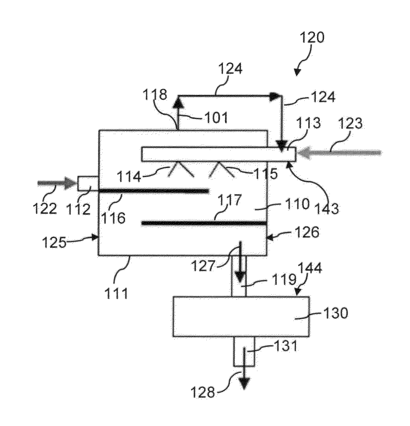
[0041]A system for the reduction and elimination of toxic gases emitted from a motor vehicle or industrial exhaust system according to one exemplary embodiment of the present invention is indicated in FIGS. 1a and 1b. Single-tier toxic gas condensation and retreatment systems 100 and 120 each includes one direct contact heat exchanger 110 and one post-treatment tank 130. Heat exchanger 110 is gas / liquid phase direct contact heat exchanger that includes housing 110 that may be made of metallic materials such as copper, iron, nickel, aluminum, titanium, chromium, combinations and alloys thereof. Preferably, heat exchanger 110 is of a rectangular or square cuboid shape. For example, in one embodiment shown in FIG. 2a, heat exchanger has a dimension of 30 cm×30 cm×30 cm.

[0042]Gaseous exhaust stream (temperature range 93-150° C. or 200-300° F.) as s...


PUM

PropertyMeasurementUnit
diameteraaaaaaaaaa
diameteraaaaaaaaaa
temperatureaaaaaaaaaa

Abstract

Apparatuses and systems for reduction and elimination of toxic gases emitted from a motor vehicle or industrial exhaust system. The systems may be single-tier or two-tier, and include at least one direct contact heat exchanger wherein exhaust gas is condensed or dissolved in cold moist air vapor. Uncondensed and undissolved gases may be recirculated into the direct contact heat exchanger to be treated again. The systems also include at least one post-treatment tank wherein condensate liquids and gas solutions are subject to agglomeration and are finally discharged into the environment as a clean liquid. The systems provided herein may complement the existing catalytic converters used in motor vehicles.

Description

CROSS REFERENCE TO RELATED APPLICATIONS[0001]This application claims the benefit of U.S. Provisional Application No. 62 / 014,237 filed Jun. 19, 2014.GRANT OF NON-EXCLUSIVE RIGHT[0002]This application was prepared with financial support from the Saudia Arabian Cultural Mission, and in consideration therefore the present inventor(s) has granted The Kingdom of Saudi Arabia a non-exclusive right to practice the present invention.BACKGROUND[0003]1. Field of the Disclosure[0004]The present invention relates to methods, apparatuses and systems for reducing and eliminating toxic gases emitted from exhaust systems.[0005]2. Description of the Related Art[0006]The “background” description provided herein is for the purpose of generally presenting the context of the disclosure. Work of the presently named inventors, to the extent it is described in this background section, as well as aspects of the description which may not otherwise qualify as prior art at the time of filing, are neither expres...

Claims


Application Information

Patent Timeline
Patent Type & Authority Patents(United States)
IPC IPC(8): B01D50/00B01D53/92B01D53/00
CPCB01D53/92B01D53/002
Inventor ALMALOWI, SAEED J.
Owner ALMALOWI SAEED J
Features
  • R&D
  • Intellectual Property
  • Life Sciences
  • Materials
  • Tech Scout
  • Unparalleled Data Quality
  • Higher Quality Content
  • 60% Fewer Hallucinations
Learn More