Motor controllers
a technology of motor controller and motor rotor, which is applied in the direction of electronic commutators, dynamo-electric machines, instruments, etc., can solve the problem that the information of inaccurate motor rotor velocity and the interpolation cannot be used at low speeds
- Summary
- Abstract
- Description
- Claims
- Application Information
AI Technical Summary
Benefits of technology
Problems solved by technology
Method used
Image


Examples
Embodiment Construction
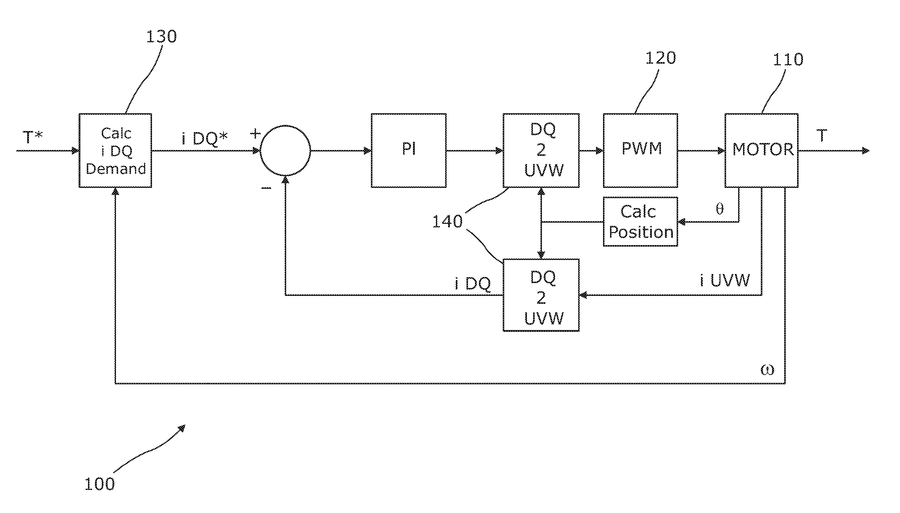
[0032]A typical closed loop motor control system 100 for a three phase motor typically has a structure as shown in FIG. 1. The motor 110 may be considered to have three phases, U, V and W, and may be connected in a star or delta configuration. Each phase is connected to an arm of a bridge drive circuit represented in FIG. 1 by the block labelled “PWM”. Each arm comprises a top switch connecting the phase to a positive supply voltage and a bottom switch connecting the phase to a negative supply voltage or ground. The six switches are turned on and off apply pulse width modulated voltages to each phase in a known manner. Several PWM strategies can be used, and for the purposes of this invention the choice of strategy is not in any way limiting.
[0033]The PWM signals for the motor phases are derived using a closed loop control, with the inputs to the control being the demanded torque T* from the motor, the measured angular velocity w of the motor rotor, the rotor position θ and the curr...
PUM
 Abstract
Description
Claims
Application Information
 - R&D
- Intellectual Property
- Life Sciences
- Materials
- Tech Scout
- Unparalleled Data Quality
- Higher Quality Content
- 60% Fewer Hallucinations
Browse by: Latest US Patents, China's latest patents, Technical Efficacy Thesaurus, Application Domain, Technology Topic, Popular Technical Reports.
© 2025 PatSnap. All rights reserved.Legal|Privacy policy|Modern Slavery Act Transparency Statement|Sitemap|About US| Contact US: help@patsnap.com