Check patentability & draft patents in minutes with Patsnap Eureka AI!

Pre-terminated fiber cable

a fiber cable and pre-terminated technology, applied in the direction of fiber mechanical structure, instruments, optics, etc., can solve the problems of increased insertion loss and easy damage during installation

Inactive Publication Date: 2016-10-18
VERIZON PATENT & LICENSING INC
View PDF2 Cites 2 Cited by
  • Summary
  • Abstract
  • Description
  • Claims
  • Application Information

AI Technical Summary

Problems solved by technology

At the installation site, typical optical cables are cut to a desired length and custom fusion spliced for proper termination, which may be time consuming and unnecessarily increase insertion loss, e.g., signal power resulting from the fusion splice.
Further, the optical fibers may include a leading end that provides an optical connection to a fiber distribution hub, but the leading end is typically fragile and unprotected thereby making it susceptible to damage during installation.

Method used


Image

  • Pre-terminated fiber cable
  • Pre-terminated fiber cable
  • Pre-terminated fiber cable

Examples


Embodiment Construction

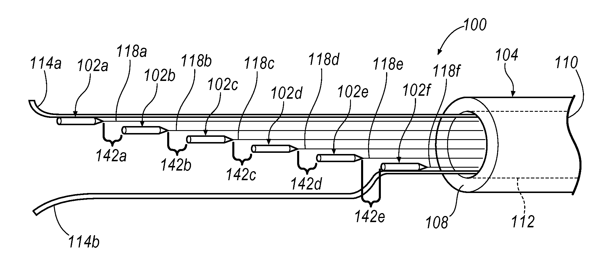
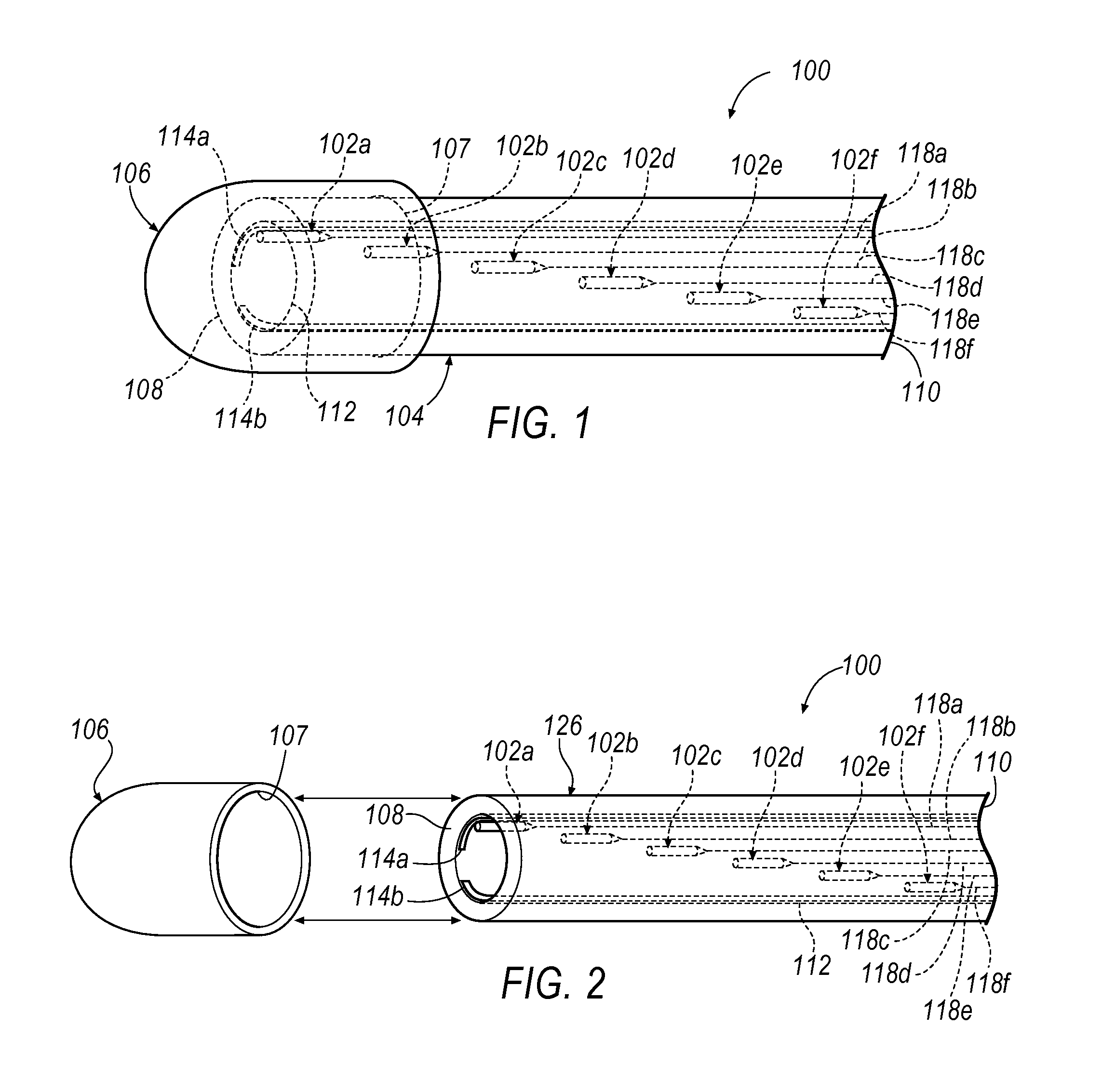
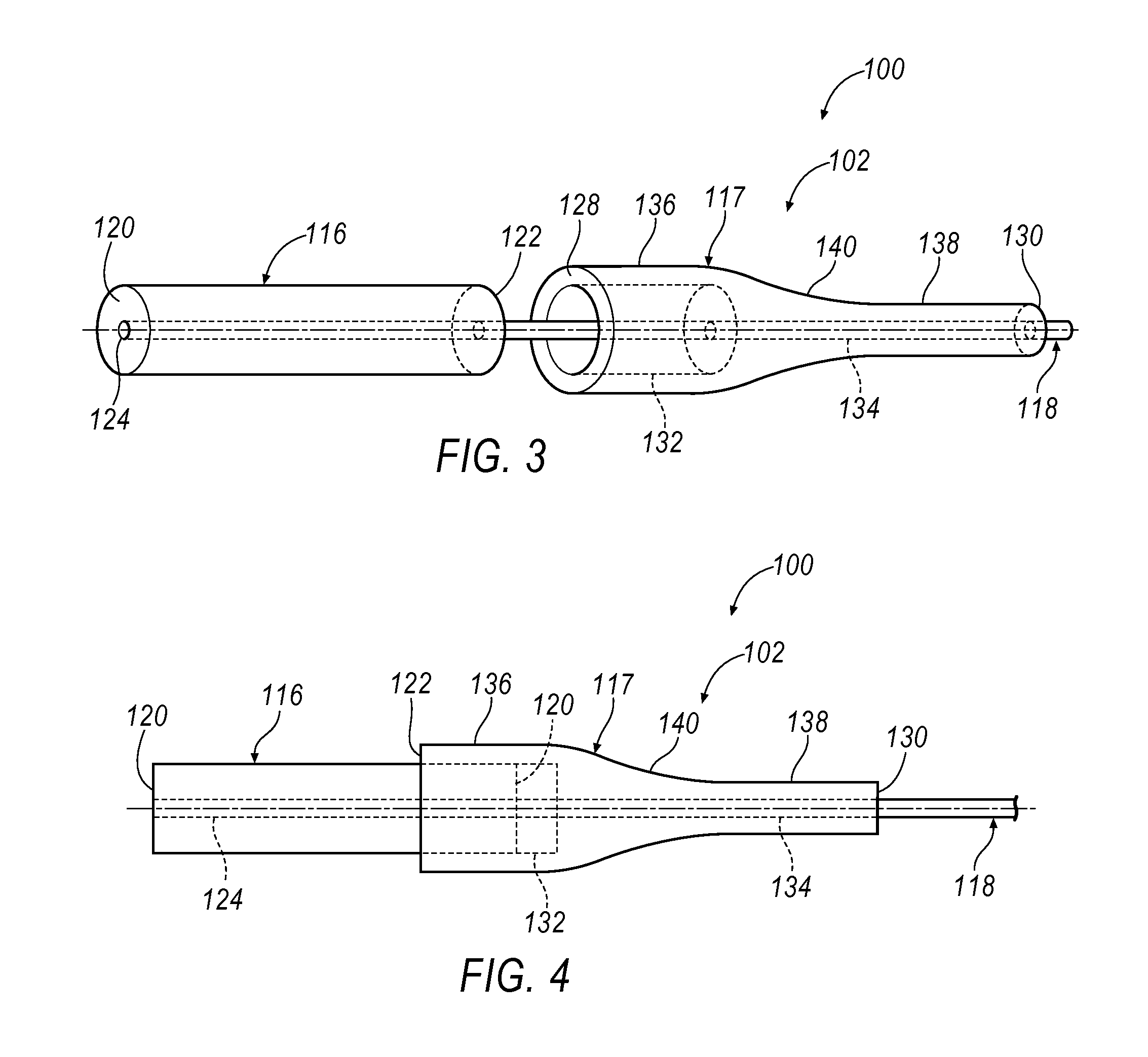
[0016]A cable assembly may include a plurality of cable connectors and a cable jacket. The plurality of cable connectors may include at least a first configuration and a second configuration. Each cable connector may include a ferrule and a cable boot. Each ferrule may have a ferrule passage between a leading end and a trailing end and may be configured to receive an optical fiber. Each cable boot may include a first end with a recess configured to receive at least a portion of the ferrule and a second end having a boot passage connected to the recess and configured to receive at least a portion of the optical fiber. The cable jacket may include a jacket passage between a first portion and a second portion and may be configured to selectively release the plurality of cable connectors in the first configuration and receive the plurality of cable connectors in the second configuration. The plurality of cable connectors may be are external to the cable jacket in the first configuration...


PUM


Abstract

A cable assembly may include a plurality of cable connectors and a cable jacket. Each cable connector may include a ferrule and a cable boot. Each ferrule may have a ferrule passage between a leading end and a trailing end and may be configured to receive an optical fiber. Each cable boot may include a first end with a recess configured to receive at least a portion of the ferrule and a second end having a boot passage connected to the recess and configured to receive at least a portion of the optical fiber. The cable jacket may include a jacket passage between a first portion and a second portion and may be configured to selectively release the plurality of cable connectors in the first configuration and receive the plurality of cable connectors in the second configuration.

Description

BACKGROUND[0001]Cable systems may include micro-ducts to route and bundle multiple sets of optical fibers in a cable jacket. These cable systems may be routed to an installation site through existing ducts in roadways and buildings. Within the cable systems, spaces are typically formed between the micro-ducts, optical fibers, and cable jacket thereby allowing airflow for the insertion and routing of the cable system with the duct acting as a guide to the installation site, which may be applied with an air jet from a blower. At the installation site, typical optical cables are cut to a desired length and custom fusion spliced for proper termination, which may be time consuming and unnecessarily increase insertion loss, e.g., signal power resulting from the fusion splice. Further, the optical fibers may include a leading end that provides an optical connection to a fiber distribution hub, but the leading end is typically fragile and unprotected thereby making it susceptible to damage ...

Claims


Application Information

Patent Timeline
Patent Type & Authority Patents(United States)
IPC IPC(8): G02B6/44G02B6/50G02B6/38G02B6/00
CPCG02B6/443G02B6/3866G02B6/4485G02B6/50G02B6/441G02B6/38875G02B6/4431
Inventor CHEN, DAVID Z.COLASANTO, CHRISTINA M.LEVENDOS, CHRISTOPHER D.
Owner VERIZON PATENT & LICENSING INC
Features
  • R&D
  • Intellectual Property
  • Life Sciences
  • Materials
  • Tech Scout
  • Unparalleled Data Quality
  • Higher Quality Content
  • 60% Fewer Hallucinations
Learn More