Check patentability & draft patents in minutes with Patsnap Eureka AI!

Universal rod holder

a universal rod and rod holder technology, applied in the field of orthopedic surgery, can solve the problems of reducing nerve function, experiencing extreme or debilitating pain,

Active Publication Date: 2017-01-17
K2M
View PDF42 Cites 0 Cited by
  • Summary
  • Abstract
  • Description
  • Claims
  • Application Information

AI Technical Summary

Benefits of technology

Enables secure positioning and manipulation of rods during spinal surgery, accommodating various diameters and shapes, enhancing surgical precision and stability by preventing torque and stress on the rods and surgical tools.

Problems solved by technology

Persons suffering from any of the above conditions typically experience extreme or debilitating pain and often times diminished nerve function.

Method used


Image

  • Universal rod holder
  • Universal rod holder
  • Universal rod holder

Examples


Embodiment Construction

[0030]Embodiments of the present disclosure are now described in detail with reference to the drawings in which like reference numerals designate identical or corresponding elements in each of the several views. As used herein, the term “clinician” refers to a doctor, a nurse, or any other care provider or user and may include support personnel. Throughout this description, the term “proximal” will refer to the portion of the device or component thereof that is closer to the clinician and the term “distal” will refer to the portion of the device or component thereof that is farther from the clinician. Additionally, in the drawings and in the description that follows, terms such as front, rear, upper, lower, top, bottom, and similar directional terms are used simply for convenience of description and are not intended to limit the disclosure.

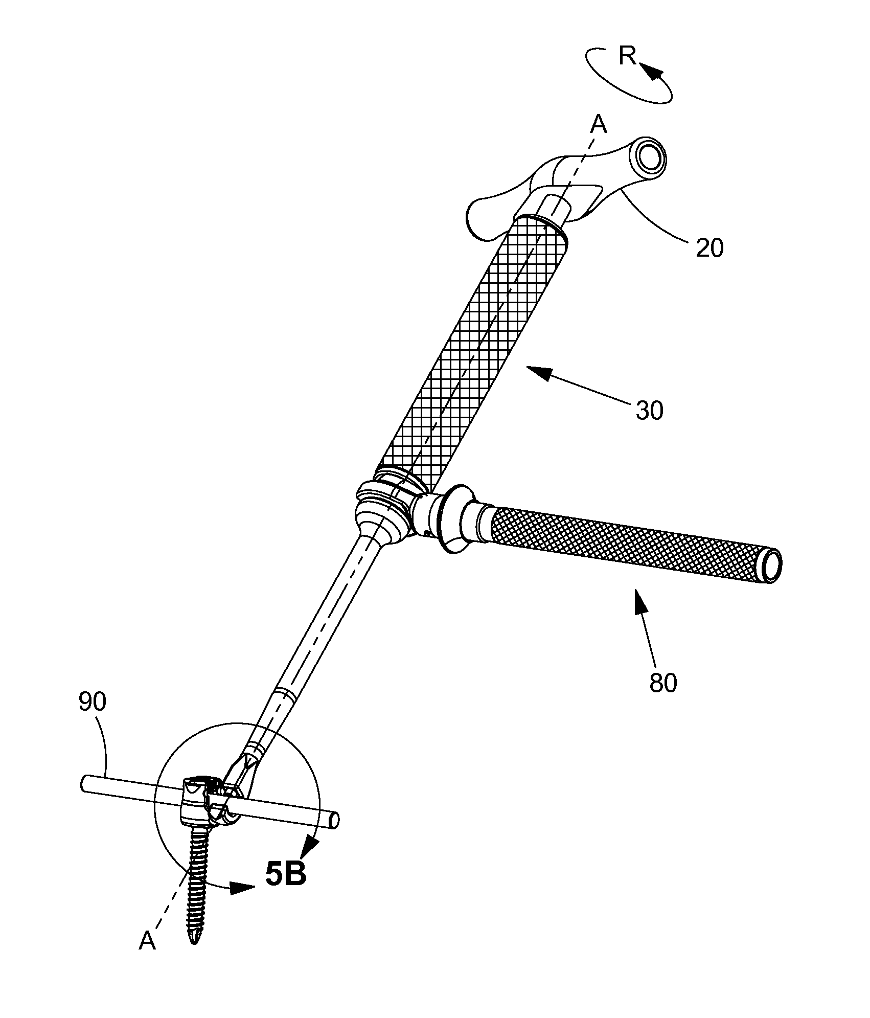
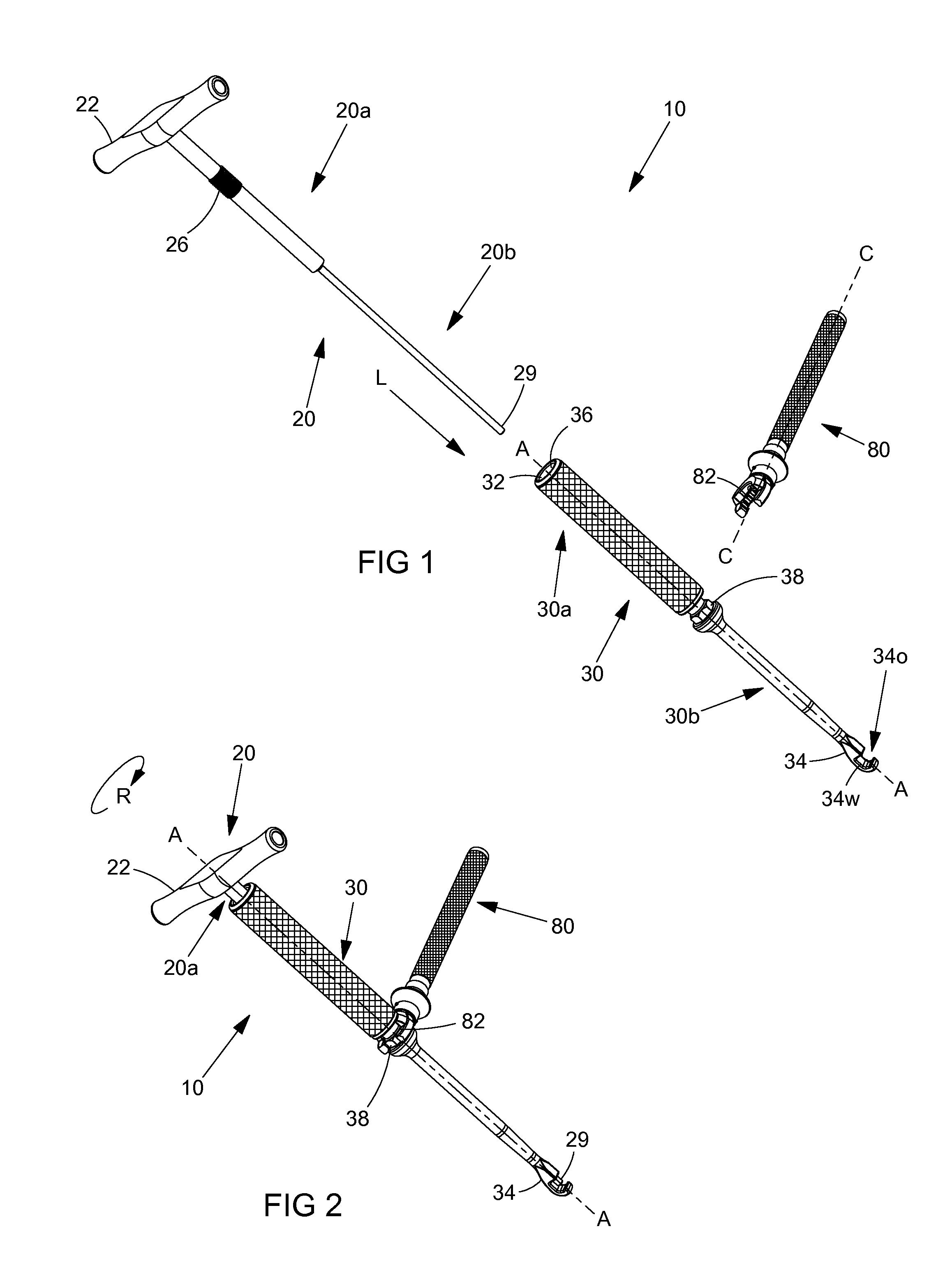
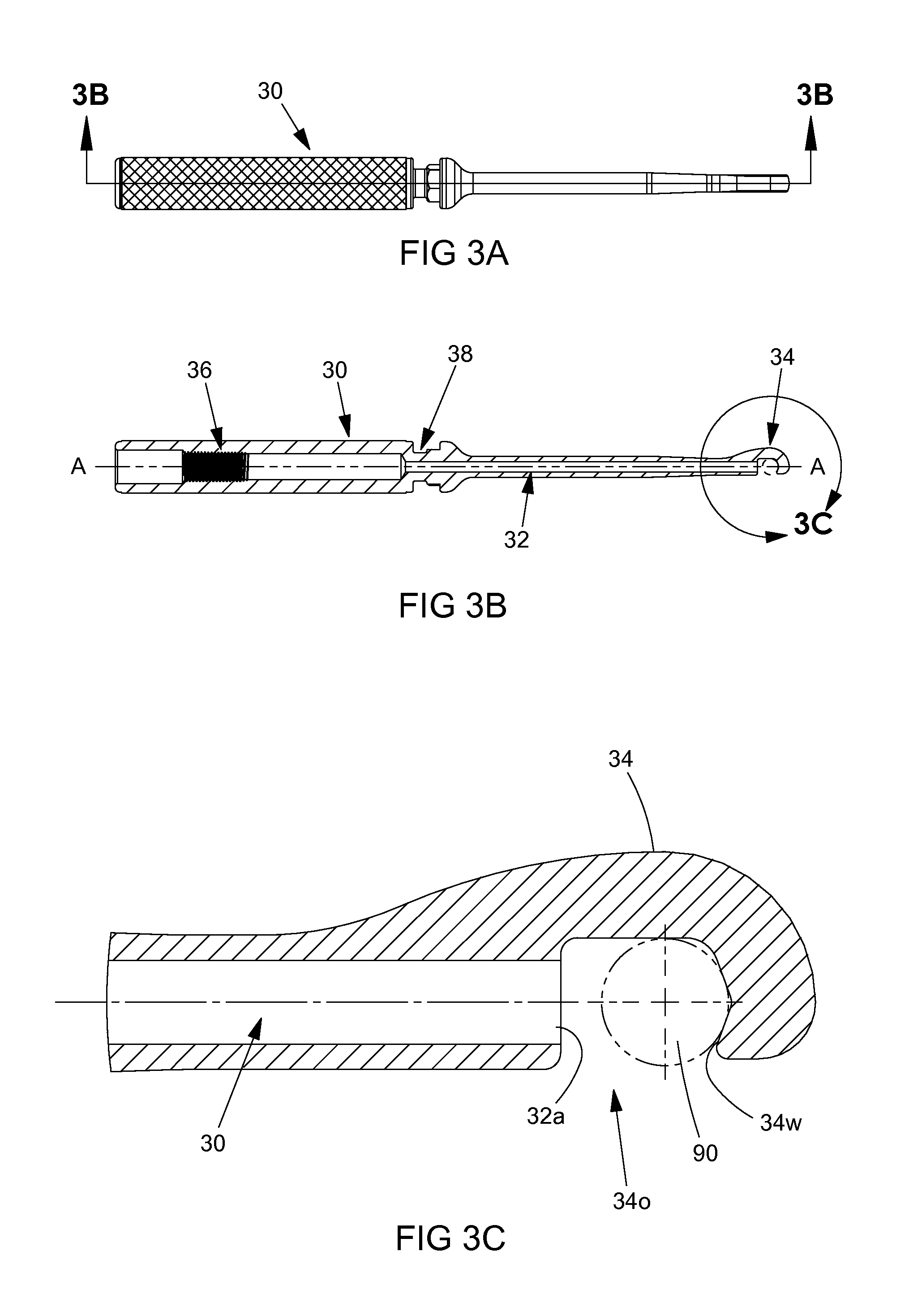
[0031]With reference to FIGS. 1 and 2, a universal rod holder 10 is provided in accordance with the present disclosure including a drive member 2...


PUM


Abstract

A universal rod holder including a drive member and an elongated shaft member. The drive member has a proximal portion and a distal portion, and may include a handle disposed on the proximal portion, external threads disposed on the proximal portion of the drive member, and a tip disposed on a distal end of the distal portion of the drive member. The elongated shaft member includes a through hole, the through hole configured to receive the drive member, internal threads disposed on an inner surface of the through hole and configured to engage the external threads, and a hook member disposed on a distal end of the shaft member. The through hole extends into an opening of the hook member. The distal portion of the drive member is configured to slide through the through hole and into the opening of the hook member to secure a rod positioned therein.

Description

CROSS-REFERENCE TO RELATED APPLICATIONS[0001]This application claims priority to, and the benefit of, U.S. Provisional Application Ser. No. 61 / 706,230 filed Sep. 27, 2012, the disclosure of which is hereby incorporated by reference in its entirety.BACKGROUND[0002]1. Technical Field[0003]The present disclosure relates to a device for use in orthopedic surgeries and, more specifically, a universal rod holder for use during spinal surgery.[0004]2. Discussion of Related Art[0005]The spinal column is a complex system of bones and connective tissues that provide support for the human body and protection for the spinal cord and nerves. The adult spine includes twenty-four vertebral bodies, which are subdivided into three areas, including seven cervical vertebrae, twelve thoracic vertebrae and five lumbar vertebrae. Between adjacent vertebral bodies is an intervertebral disc that cushions and dampens the various translational and rotational forces exerted upon the spinal column.[0006]There ...

Claims


Application Information

Patent Timeline
Patent Type & Authority Patents(United States)
IPC IPC(8): A61B17/70
CPCA61B17/7083A61B17/7002A61B17/701
Inventor MCCLINTOCK, LARRYSTRAUSS, KEVIN R.
Owner K2M
Features
  • R&D
  • Intellectual Property
  • Life Sciences
  • Materials
  • Tech Scout
  • Unparalleled Data Quality
  • Higher Quality Content
  • 60% Fewer Hallucinations
Learn More