Check patentability & draft patents in minutes with Patsnap Eureka AI!

Processing apparatus for guiding workpiece using bellows with floating means

a technology of processing apparatus and workpiece, which is applied in mechanical apparatus, manufacturing tools, transportation and packaging, etc., can solve problems such as damage to each support member, and achieve the effect of improving productivity

Active Publication Date: 2017-04-25
DISCO CORP
View PDF25 Cites 1 Cited by
  • Summary
  • Abstract
  • Description
  • Claims
  • Application Information

AI Technical Summary

Benefits of technology

[0009]It is therefore an object of the present invention to provide a processing apparatus which can prevent the slack of the expansible and contractable bellows means mounted on the workpiece holding means so as to cover the feeding means and adapted to be moved together with the workpiece holding means in the feeding direction, wherein even when the workpiece holding means is moved in the feeding direction at a high speed, the support members for supporting the bellows means can follow the movement of the workpiece holding means, thereby preventing damage to the support members.
[0013]As described above, the processing apparatus according to the present invention includes the expansible and contractable bellows means mounted on the workpiece holding means for covering the area of movement of the workpiece holding means in the feeding direction and the guide means for guiding the expansion and contraction of the bellows means in the feeding direction. The guide means includes the opening for allowing the movement of the workpiece holding means in the feeding direction, the gutter extending in the feeding direction adjacent to the opening, and the end wall provided at an end of the opening in the feeding direction. The bellows means includes the first connecting member connected to the workpiece holding means, the second connecting member connected to the end wall of the guide means, and the bellows member extending between the first connecting member and the second connecting member. The processing apparatus further includes the floating means for floating the bellows member along the gutter of the guide means in a noncontact manner. Accordingly, no friction is generated between the bellows means and the guide means, so that even when the feed speed of the workpiece holding means is high, the bellows means can follow the movement of the workpiece holding means, thereby improving the productivity.

Problems solved by technology

However, when the workpiece holding means holding the workpiece is moved in the feeding direction at a high speed in order to improve the productivity, there arises a problem such that each support member provided on the bellows means cannot follow the high feed speed of the workpiece holding means, causing damage to each support member.

Method used


Image

  • Processing apparatus for guiding workpiece using bellows with floating means
  • Processing apparatus for guiding workpiece using bellows with floating means
  • Processing apparatus for guiding workpiece using bellows with floating means

Examples


Embodiment Construction

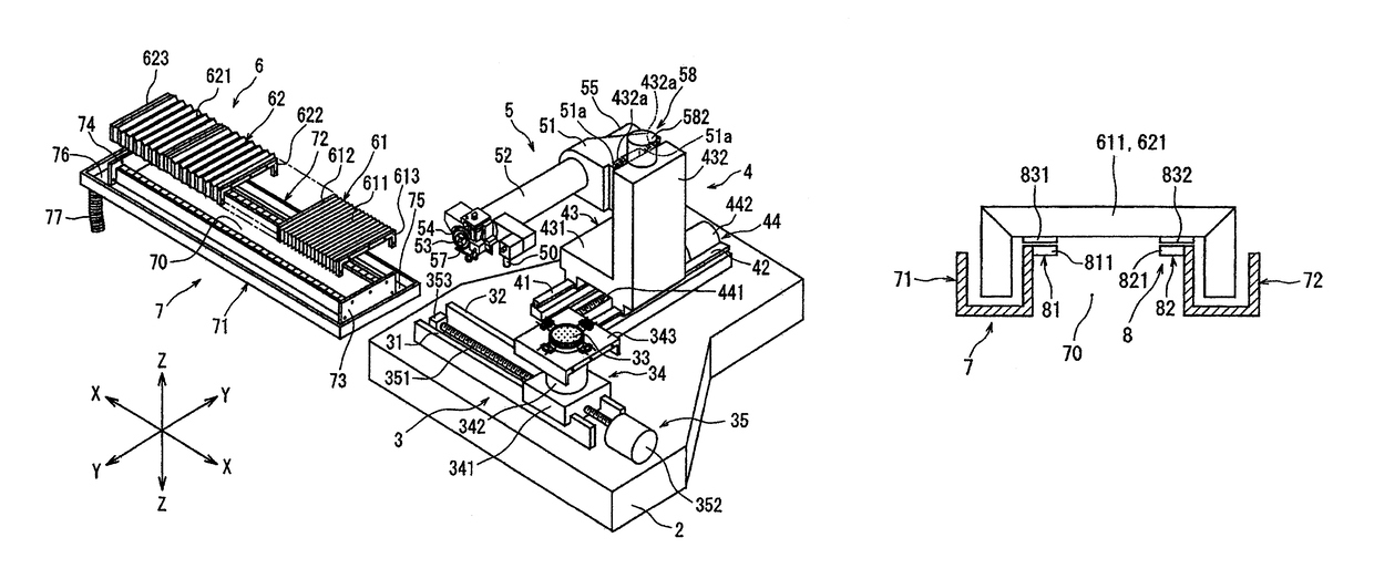
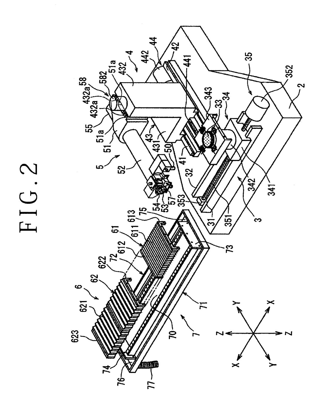
[0021]A preferred embodiment of the processing apparatus according to the present invention will now be described in detail with reference to the attached drawings. FIG. 1 is a perspective view of a cutting apparatus according to this preferred embodiment. The cutting apparatus shown in FIG. 1 includes a substantially boxlike base housing 1. As shown in FIG. 2, there are provided in the base housing 1 a stationary base 2, a chuck table mechanism 3 for holding a workpiece, the chuck table mechanism 3 being provided on the stationary base 2 so as to be movable in a feeding direction (X direction) shown by an arrow X, a spindle supporting mechanism 4 provided on the stationary base 2 so as to be movable in an indexing direction (Y direction) shown by an arrow Y perpendicular to the X direction, and a spindle unit 5 as cutting means provided on the spindle supporting mechanism 4 so as to be movable in a cutting direction (Z direction) shown by an arrow Z perpendicular to both the X dire...


PUM


Abstract

A processing apparatus including an expansible and contractable bellows unit mounted on a workpiece holding unit for covering an area of movement of the workpiece holding unit in a feeding direction and a guide unit for guiding the expansion and contraction of the bellows unit in the feeding direction. The guide unit has an opening for allowing the movement of the workpiece holding unit in the feeding direction and a gutter extending in the feeding direction adjacent to the opening. The bellows unit has a bellows member having one end connected to the workpiece holding unit and the other end connected to the guide unit. The processing apparatus further includes a floating unit for floating the bellows member along the gutter of the guide unit in a noncontact manner.

Description

BACKGROUND OF THE INVENTION[0001]Field of the Invention[0002]The present invention relates to a processing apparatus such as a cutting apparatus for cutting a workpiece such as a semiconductor wafer and a laser processing apparatus for performing laser processing to such a workpiece.[0003]Description of the Related Art[0004]In a semiconductor device fabrication process, a plurality of crossing division lines are formed on the front side of a substantially disk-shaped semiconductor wafer to thereby define a plurality of separate regions where a plurality of semiconductor devices such as ICs and LSIs are respectively formed. The semiconductor wafer thus having the plural semiconductor devices is cut along the division lines to thereby divide the regions where the semiconductor devices are formed from each other, thus manufacturing the individual semiconductor devices as chips. Further, a gallium nitride compound semiconductor or the like is formed on the front side of a sapphire subst...

Claims


Application Information

Patent Timeline
Patent Type & Authority Patents(United States)
IPC IPC(8): B23Q5/34B23Q11/08F16L11/11H01L21/67H01L21/677
CPCF16L11/11B23Q11/0816H01L21/67092H01L21/67709
Inventor FUJISAWA, SHINICHIMATSUYAMA, TOSHIFUMISUWANO, JUN
Owner DISCO CORP
Features
  • R&D
  • Intellectual Property
  • Life Sciences
  • Materials
  • Tech Scout
  • Unparalleled Data Quality
  • Higher Quality Content
  • 60% Fewer Hallucinations
Learn More