Check patentability & draft patents in minutes with Patsnap Eureka AI!

Combination lock

a technology of combinator lock and lock body, which is applied in the field of combinator lock, can solve the problems of wasting a lot of time, frustrated assembly process, and inability to reduce manufacturing costs, and achieve the effect of convenient assembly and manufacturing

Active Publication Date: 2017-05-30
YANG YAO KUN
View PDF11 Cites 1 Cited by
  • Summary
  • Abstract
  • Description
  • Claims
  • Application Information

AI Technical Summary

Benefits of technology

The design allows for efficient rotation and pausing of number disks, reducing assembly time and manufacturing costs while ensuring stable operation, making the combination lock easier to produce and assemble.

Problems solved by technology

However, the number of the springs 107 and the push members 108 are so tiny so that the assembling processes can be frustrated and take a lot of time.
The manufacturing cost cannot be reduced.

Method used


Image

  • Combination lock
  • Combination lock
  • Combination lock

Examples


Embodiment Construction

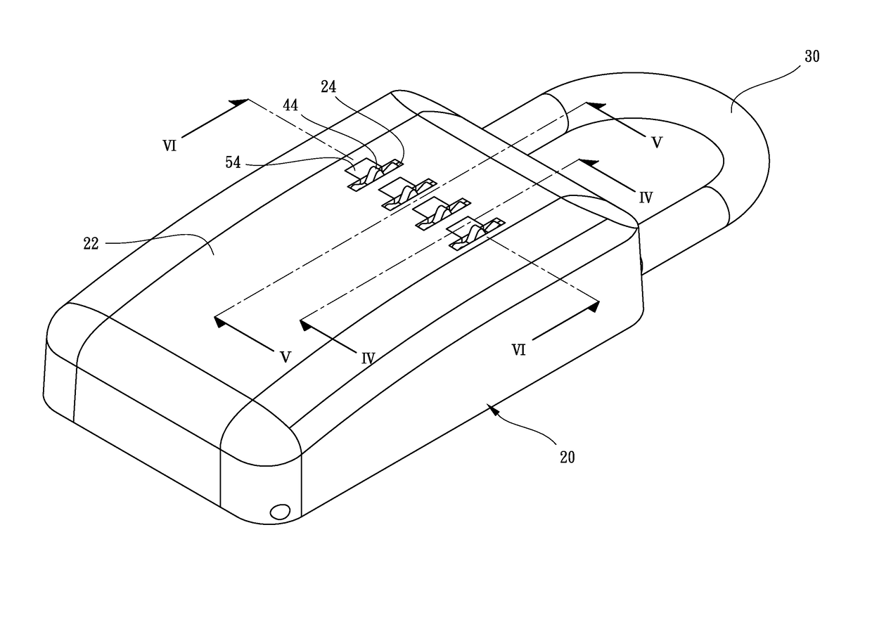
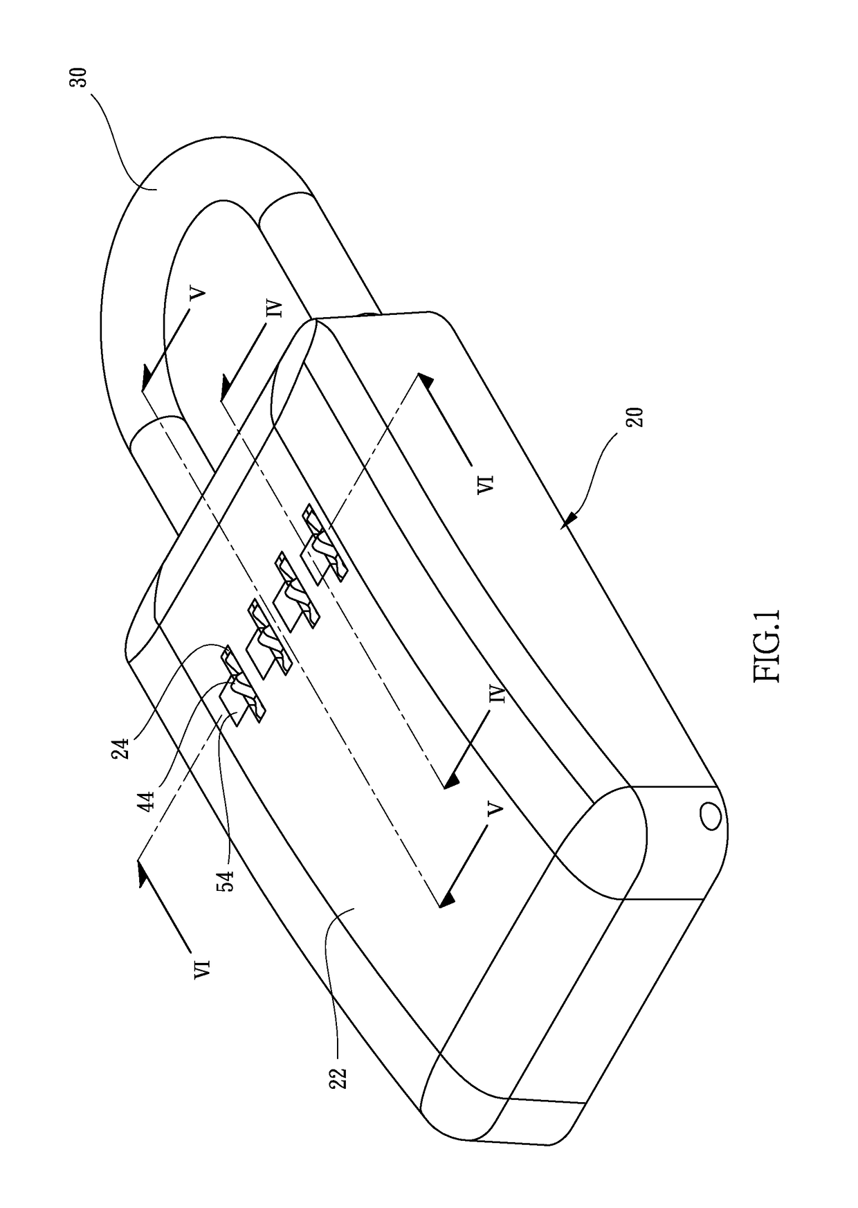
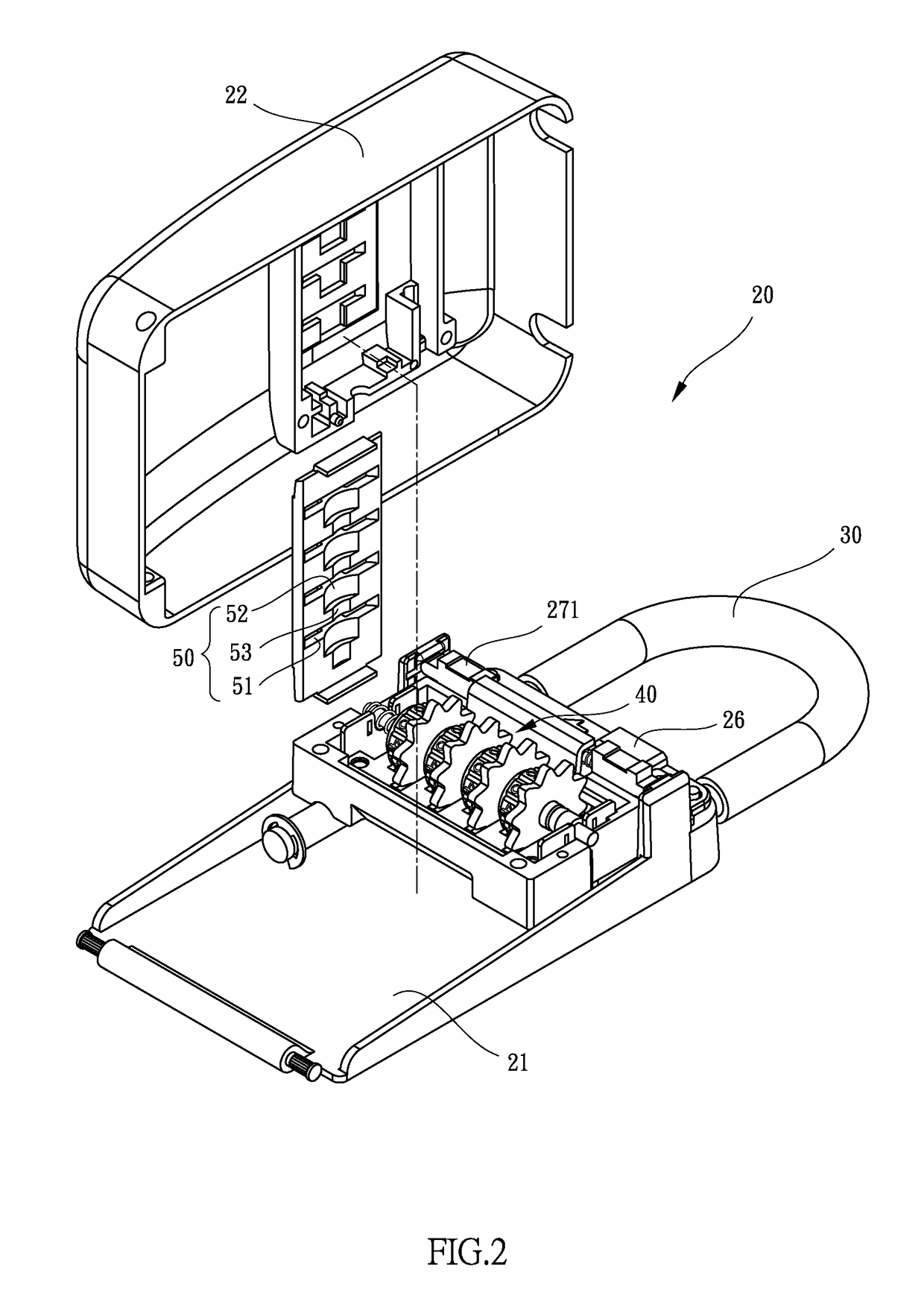
[0019]Referring to FIGS. 1 to 3, the combination lock of the present invention comprises a casing 20 having a base 21 and a cover 22 which is mounted to the open side of the base 21. The base 21 has a space 23 defined therein, and the cover 22 has multiple first side holes 24 and multiple openings 25, each opening 25 communicates with one of the first side holes 24 corresponding thereto. A shackle 30 is connected to the casing 20, one end of the shackle 30 is connected to the casing 20, and the other end of the shackle 30 is removably inserted into the casing 20 so as to form the locked status and the opened status.

[0020]A number disk unit 40 has a seat 41, a shaft 42, multiple number disks 43, multiple driving wheels 45 and multiple rotary disks 44. The shaft 42 is pivotably connected to the seat 41. Each driving wheel 45 has a circular disk 451 and a tubular portion 452 which extends from the circular disk 451. Each tubular portion 452 extends through the number disk 43 and the ro...


PUM


Abstract

A combination lock includes a casing, a number disk unit, a restriction member located above the number disk unit, and a resilient member cooperated with the number disk unit. The number disk unit has multiple rotary disks and multiple number disks, each number disk has multiple mark areas and multiple grooves located alternatively to the mark areas. The resilient member has multiple engaging portions which are resiliently engaged with the grooves of the number disks so as to ensure that each of the number disks is rotated one mark area and the engaging portion is engaged with the groove to pause the number disk. The combination lock is easily assembled and manufactured.

Description

BACKGROUND OF THE INVENTION[0001]1. Fields of the Invention[0002]The present invention relates to a combination lock, and more particularly, to a combination lock that is easily manufactured and the number disks are conveniently rotated.[0003]2. Descriptions of Related Art[0004]The conventional combination lock 1 is disclosed in FIG. 7 and comprises a casing 101 which has multiple partitions 102 defined therein. Each partition 102 has a number disk 103 received therein and each number disk 103 has multiple recesses 105 formed along an outer periphery of one end thereof. Each number disk 103 has multiple numbers formed thereon. Each partition 102 has a room 106 in which a spring 107 is received. A push member 108 is biased by the spring 107 corresponding thereto and each push member 108 has a protrusion which is engaged with one of the recesses 105 of the number disk 103 corresponding thereto. A plate 109 is mounted above the number disks 103, and a cover 100 is mounted to the casing...

Claims


Application Information

Patent Timeline
Patent Type & Authority Patents(United States)
IPC IPC(8): E05B37/02
CPCE05B37/02E05B37/025
Inventor YANG, YAO-KUN
Owner YANG YAO KUN
Features
  • R&D
  • Intellectual Property
  • Life Sciences
  • Materials
  • Tech Scout
  • Unparalleled Data Quality
  • Higher Quality Content
  • 60% Fewer Hallucinations
Learn More