Supercharge Your Innovation With Domain-Expert AI Agents!

LED lamp

a technology of led lamps and led lamps, which is applied in the direction of semiconductor lamps, lighting and heating apparatus, semiconductor devices for light sources, etc., can solve the problems that led lamps for fluorescent light have not been widely distributed, and achieve the effect of high efficiency of led lighting

Inactive Publication Date: 2017-08-15
KUMHO ELECTRIC INC +1
View PDF4 Cites 16 Cited by
  • Summary
  • Abstract
  • Description
  • Claims
  • Application Information

AI Technical Summary

Benefits of technology

Enables the use of LED lamps with existing ballast stabilizers for fluorescent lights, reducing the need for new installations and maintaining high efficiency without altering the conventional ballast stabilizer, thus facilitating the transition from fluorescent to LED lighting.

Problems solved by technology

Accordingly, there is a problem that should replace a wiring within the lamp device and thus an LED lamp for fluorescent light has not been widely spread.

Method used


Image

  • LED lamp
  • LED lamp
  • LED lamp

Examples


Embodiment Construction

[0017]Exemplary embodiments of the present invention will be described below in detail with reference to the accompanying drawings. Wherever possible, the same reference numerals will be used to refer to the same elements throughout the specification, and a duplicated description thereof will be omitted. It will be understood that although the terms “first”, “second”, etc. are used herein to describe various elements, these elements should not be limited by these terms. These terms are only used to distinguish one element from another element.

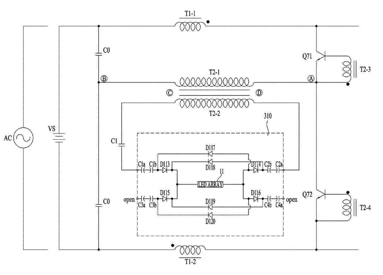
[0018]FIG. 1 is a circuit diagram of an LED lamp according to an exemplary embodiment of the present invention.

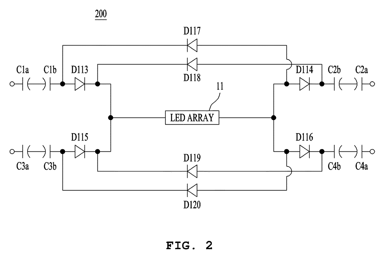
[0019]Referring to FIG. 1, an LED lamp 100 according to the present exemplary embodiment includes an LED array 11 and capacitor pairs (C1a and C1b, C2a and C2b, C3a and C3b, and C4a and C4b), which are a capacitive element and may have first to fourth connection pins, which are external connection pins.

[0020]The LED array 11 has a stru...


PUM


Abstract

Provided is a Light Emitting Diode (LED) lamp. The LED lamp includes: four external connection pins including at least two connection pins connected to a ballast stabilizer for a fluorescent lamp; an LED array in which a plurality of LEDs are connected in series; and at least a pair of capacitors formed between the LED array and the external connection pin, wherein in each of the at least a pair of capacitors, two polarized capacitors are connected in series with a back-to-back method.

Description

CROSS-REFERENCE(S) TO RELATED APPLICATION[0001]This application claims priority of Korean Patent Application No. 10-2015-0139518, filed on Oct. 5, 2015, in the Korean Intellectual Property Office, which is hereby incorporated by reference in its entirety.BACKGROUND OF THE INVENTION[0002]Field of the Invention[0003]The present invention relates to a Light Emitting Diode (LED) lamp, and more particularly, to an LED lamp connected to a ballast stabilizer for fluorescent light to be driven regardless of a kind of a ballast stabilizer for fluorescent light.[0004]Description of the Related Art[0005]With the development of technology, light efficiency of an LED used only for small power instruction light in the past has been improved to use in an actual life. Further, as an environmentally-friendly light source that does not contain mercury unlike other light sources, an LED has been spotlighted as a next generation light source for backlight for a mobile terminal, backlight for an LCD TV,...

Claims


Application Information

Patent Timeline
Patent Type & Authority Patents(United States)
IPC IPC(8): F21K9/27H05B33/08H05B44/00
CPCF21K9/27H05B33/083H05B33/0845H05B33/0884H05B33/0809F21Y2115/10Y02B20/30H05B45/39H05B45/50H05B45/59H05B45/48
Inventor PARK, MYUNG KOO
Owner KUMHO ELECTRIC INC
Features
  • R&D
  • Intellectual Property
  • Life Sciences
  • Materials
  • Tech Scout
  • Unparalleled Data Quality
  • Higher Quality Content
  • 60% Fewer Hallucinations
Learn More