Check patentability & draft patents in minutes with Patsnap Eureka AI!

Cover for centrifugal filter

a centrifugal filter and cover technology, applied in centrifuges, rotary centrifuges, etc., can solve the problems of emulsion and inability to remove water from oil

Inactive Publication Date: 2017-08-22
SHIN HEUNG PRECISION
View PDF18 Cites 2 Cited by
  • Summary
  • Abstract
  • Description
  • Claims
  • Application Information

AI Technical Summary

Benefits of technology

The cover design reduces oil leakage, ensures even distribution of mixed gases and water, and maintains stable gas flow by preventing concentration and leakage, enhancing the efficiency of the centrifugal filtration process.

Problems solved by technology

Although the above-described centrifugal filter can separate and remove impurities in oil, it cannot remove water from the oil.
However, the centrifugal filter has an inconsistency in that it requires supplying water for the separation of water or removal of the impurities from oil, and further has a disadvantage in that an emulsion occurs due to the increase of a region on which water and oil come into contact with each other.

Method used


Image

  • Cover for centrifugal filter
  • Cover for centrifugal filter
  • Cover for centrifugal filter

Examples


Embodiment Construction

[0033]Hereinafter, an exemplary embodiment of the present invention will be described in detail with reference to the accompanying drawings. In the following description of the present invention, detailed descriptions of known functions and components incorporated herein will be omitted when it may make the subject matter of the present invention unclear.

[0034]FIG. 3 is a perspective view showing the structure of a cover for a centrifugal filter according to the present invention; FIG. 4 is a sectional view showing the structure of the cover for the centrifugal filter according to the present invention; FIG. 5 is a sectional view taken along line 5-5′ of FIG. 4; and FIG. 6 is a sectional view taken along line 6-6′ of FIG. 4.

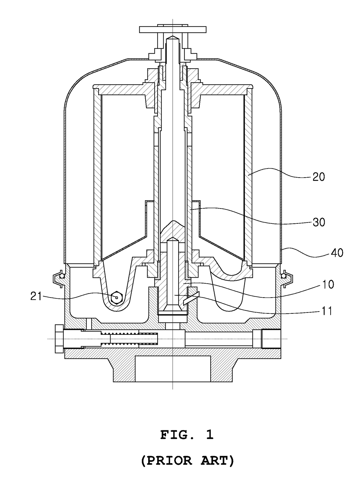
[0035]When oil filtered in a rotor 20 is jetted through a nozzle 21, the cover for the centrifugal filter according to the present invention allows water separated from the oil to be discharged with mixed gas, and includes an inner cover 110, an outer cover 120, ...


PUM


Abstract

A cover for a centrifugal filter, in which when water separated from oil is discharged through outlets provided in covers, can reduce the amount of oil leaking out with mixed gas and water. The cover constitutes the centrifugal filter by covering a rotor that rotates so as to filter impurities contained in oil by using a centrifugal force. The rotor is provided with at least one nozzle through which filtered oil is jetted. The cover includes: an inner cover configured to cover the rotor and including a first outlet and a first inlet; an outer cover provided outside the inner cover; and an oil leak prevention member provided in the first outlet.

Description

TECHNICAL FIELD[0001]The present invention relates generally to a cover for a centrifugal filter. More particularly, the present invention relates to a cover for a centrifugal filter, in which when oil filtered in the centrifugal filter is jetted through a nozzle of a rotor, the cover enables water separated from the oil to be safely discharged to the outside of the centrifugal filter, and further enables dehydrated mixed gas to be safely introduced into the centrifugal filter.BACKGROUND ART[0002]In general, a centrifugal filter is a device performing the functions of separation, purification, and concentration of liquids that are different in components and specific gravities by using a centrifugal force. The centrifugal filter is also used in filtering impurities out of oil (lubricants or fuel oil), used in engines, and used in various kinds of mechanical devices.[0003]FIG. 1 is a sectional view showing the structure of the centrifugal filter according to a conventional art.[0004]...

Claims


Application Information

Patent Timeline
Patent Type & Authority Patents(United States)
IPC IPC(8): B04B7/04B04B9/06B04B3/00B04B7/02B04B5/00
CPCB04B7/04B04B3/00B04B5/005B04B7/02B04B9/06
Inventor KIM, YONG KEUNEUM, HO JINYE, KYO HYE
Owner SHIN HEUNG PRECISION
Features
  • R&D
  • Intellectual Property
  • Life Sciences
  • Materials
  • Tech Scout
  • Unparalleled Data Quality
  • Higher Quality Content
  • 60% Fewer Hallucinations
Learn More