Supercharge Your Innovation With Domain-Expert AI Agents!

Technique for automatically tracking an object by a camera based on identification of an object

a technology of automatic tracking and object identification, applied in the field of tracking objects, can solve problems such as the problem of multiple objects being tracked, and achieve the effect of solving problems such as problems such as problems such as problems such as the problem of multiple objects

Active Publication Date: 2017-08-22
GRASS VALLEY CANADA
View PDF74 Cites 8 Cited by
  • Summary
  • Abstract
  • Description
  • Claims
  • Application Information

AI Technical Summary

Benefits of technology

Enables accurate tracking of multiple objects without the need for multiple IR transmitters or embedded systems, improving the precision and efficiency of camera movements to keep objects centered within the field of view.

Problems solved by technology

However, tracking of multiple objects can prove problematic, such as in the case when a single robotic camera serves to capture the image of several different on-air talent, as occurs when the camera moves to capture the image of a news anchor at one instant, and a weather reporter at a different instant.
This IR system also suffers from the disadvantage that the anchor person has to wear an embedded system that should be located at the center of the head to have an accurate estimate of the head position

Method used


Image

  • Technique for automatically tracking an object by a camera based on identification of an object
  • Technique for automatically tracking an object by a camera based on identification of an object
  • Technique for automatically tracking an object by a camera based on identification of an object

Examples


Embodiment Construction

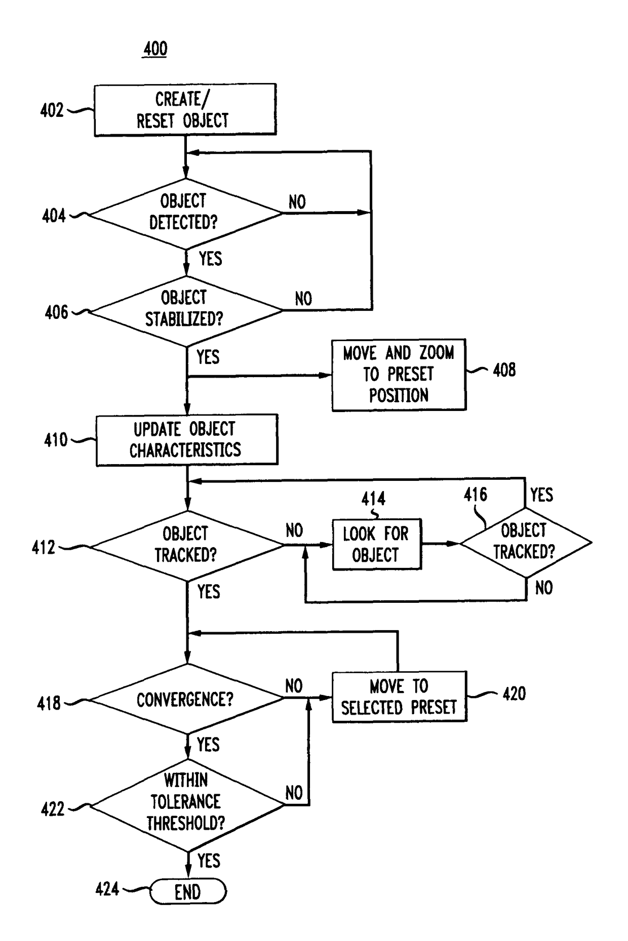
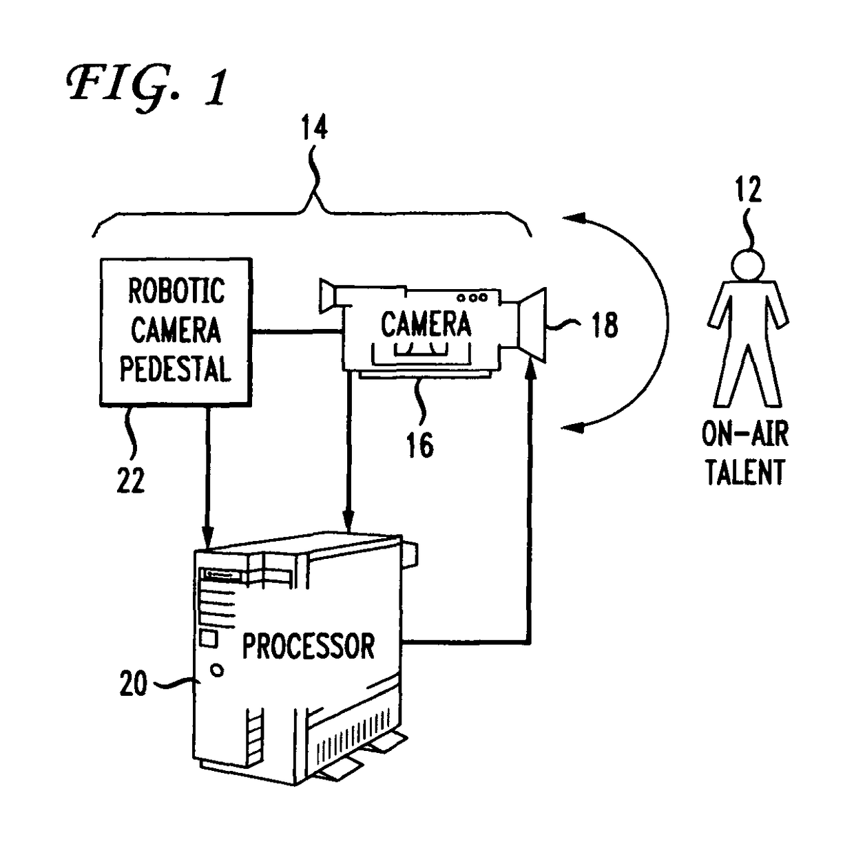
[0013]FIG. 1 depicts a block schematic diagram of an exemplary system 10 for automatically tracking an object 12, such as on-air talent, in accordance with the present principles. The on-air talent 12 could take the form of a newscaster, sports reporter, or weatherman in connection with a production of a television news program, or on-air talent in connection with other types of television programming (e.g., a game show host).

[0014]The system 10 includes a robotic camera assembly 14, such as the “Camerman” robotic camera assembly available from Thomson Grass Valley, Jacksonville, Fla. The robotic camera assembly 14 typically includes a television camera 16 that carries a zoom lens 18 whose functions, such as iris and zoom, respond to signals supplied by a processor 20, such as but not limited to, a personal computer or the like. Thus, the lens 18 has a variable zoom function. The processor 20 also controls a robotic camera pedestal 22 which has the capability of displacing the camer...


PUM


Abstract

Automatic tracking by a camera (16) of an object (12) such as on-air talent appearing in a television show commences by first determining whether the object lies within the camera field of view matches a reference object. If so, tracking of the object then occurs to maintain the object in fixed relationship to a pre-set location in the camera's field of view, provided the designated object has moved more than a threshold distance from the pre-set location.

Description

CROSS REFERENCE INFORMATION[0001]This application claims the benefit, under 35 U.S.C. §365 of International Application PCT / US2009 / 002286, filed Apr. 13, 2009 , which was published in accordance with PCT Article 21(2) on Oct. 22, 2009 in English and which claims priority under 35 U.S.C. 119(e) to U.S. Provisional Patent Application Ser. No. 61 / 124,094 filed Apr. 14, 2008 , the teachings of which are incorporated herein.TECHNICAL FIELD[0002]This invention relates to a technique for tracking an object whose image is captured by a camera or the like.BACKGROUND ART[0003]Live production of a television program such as a news show often requires one or more television cameras to capture the image of different “on-air” talent, such as a news anchor, weather reporter and / or sports reporter. In the past, a camera operator would manually operate each television camera. Such manual operation often entailed moving the camera to different positions within a television studio to make sure that th...

Claims


Application Information

Patent Timeline
Patent Type & Authority Patents(United States)
IPC IPC(8): H04N7/18G06T7/20G01S3/786H04N5/232
CPCG06T7/20G01S3/7865H04N5/23203H04N5/23216G06T2207/10016G06T2207/30201H04N23/66H04N23/62
Inventor HOLTZ, ALEXMATICS, SCOTT RAYMONDOISEL, LIONEL
Owner GRASS VALLEY CANADA
Features
  • R&D
  • Intellectual Property
  • Life Sciences
  • Materials
  • Tech Scout
  • Unparalleled Data Quality
  • Higher Quality Content
  • 60% Fewer Hallucinations
Learn More