Check patentability & draft patents in minutes with Patsnap Eureka AI!

Home network identification method and device

a technology for identification methods and home networks, applied in powerline communications applications, data switching networks, transmission/receiving using protocols, etc., can solve problems such as difficult identification of the size and structure of the home network, and inconvenient use of home network topology identification methods

Active Publication Date: 2017-09-05
WSOU INVESTMENTS LLC
View PDF10 Cites 0 Cited by
  • Summary
  • Abstract
  • Description
  • Claims
  • Application Information

AI Technical Summary

Benefits of technology

[0009]This relationship can be exploited to identify a network size and its structure by estimating the network signature through its channel delay spread. Furthermore, the network identification is improved by correlating an estimated network signature and network parameters obtained from the home network devices.
[0018]The methods can allow for a reliable and fast identification of the home network topology. By correlating the information that is extracted from the channel delay spread function with the at least one home network parameter, further topology parameters such as connected branches can unambiguously be derived for confirmation of assumptions regarding the network topology, and can be used as a basis of further analysis. Structural properties of the home network, such as branches, can be reliably identified and used for further fitting an estimated network topology to the measured data.
[0031]In another embodiment, the at least one home network parameter that is correlated with the estimated blind network topology is selected from a group of parameters consisting of bit error rate, device identity, time stamp, channel gain, domain identity, and data rate. The correlation of any of these parameters to the estimated blind network topology can improve the reliability of the obtained information on the home network topology and can shorten a processing time required for an identification process.
[0032]In a further preferred embodiment, the collected home network parameter is forwarded to a remote management center device that is provided to carry out the method. By that, the costs of a home network can be substantially reduced and the effort of bringing service staff to the site of the home network can be avoided. This embodiment can also allow for a more frequent analysis of the home network, providing an option of preventive maintenance. Preferably, the home network parameter can be collected and forwarded to the remote management center device by the residential gateway.
[0034]The processing time required for home network topology identification can advantageously be kept short if in step (d) of the method only major reflections of the channel delay spread function are taken into account. Theoretically, there is an infinite number of reflections, so that sorting out irrelevant ones can substantially reduce the processing time. The phrase “major reflections”, as used in this application, shall be understood particularly to include those reflections which correspond to an upper 70% of amplitudes, preferably to an upper 60% and, mostly preferred, to an upper 50% of amplitudes that are sorted according to size.
[0035]In another aspect, a management center device is provided that is remote from a home network having a plurality of network devices with a residential gateway among them, wherein the management center device is provided to carry out steps (1a) to (1e) of the described method. This can allow for a frequent, automated analysis of the home network at reduced costs and with a high reliability.

Problems solved by technology

To date, troubleshooting and diagnostics of in-house networks, also known as home networks, from a remote location outside of the network is a challenging task.
In particular, the identification of size and structure of a home network is challenging due to a potential large number of branches and terminations within the home network.
When considering more complex home network topologies, such as in particular Power Line Communication (PLC) networks including a large number of nodes and branches, available solutions of home network topology identification methods are not as efficient as is desirable from a service operator perspective, due to a much more complex channel gain function and the huge number of reflections occurring in all branches of the home network.

Method used


Image

  • Home network identification method and device
  • Home network identification method and device
  • Home network identification method and device

Examples


Embodiment Construction

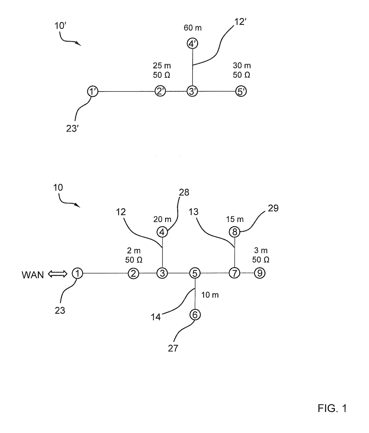
[0045]Examples of home networks 10, 10′, 11, 11′ have already been introduced in the background art section. In the following, the application of an embodiment of the home network topology identification method to the home networks 10 and 10′ shown in FIG. 1 will be described.

[0046]A lower part of FIG. 1 shows a home network 10 having a plurality of network devices 27, 28, 29 and a residential gateway 23 that is provided to connect the home network 10 with a wide area network WAN such as the Internet. The home network 10 is designed as a power line network with nine nodes 1-9 and three branches 12, 13, 14.

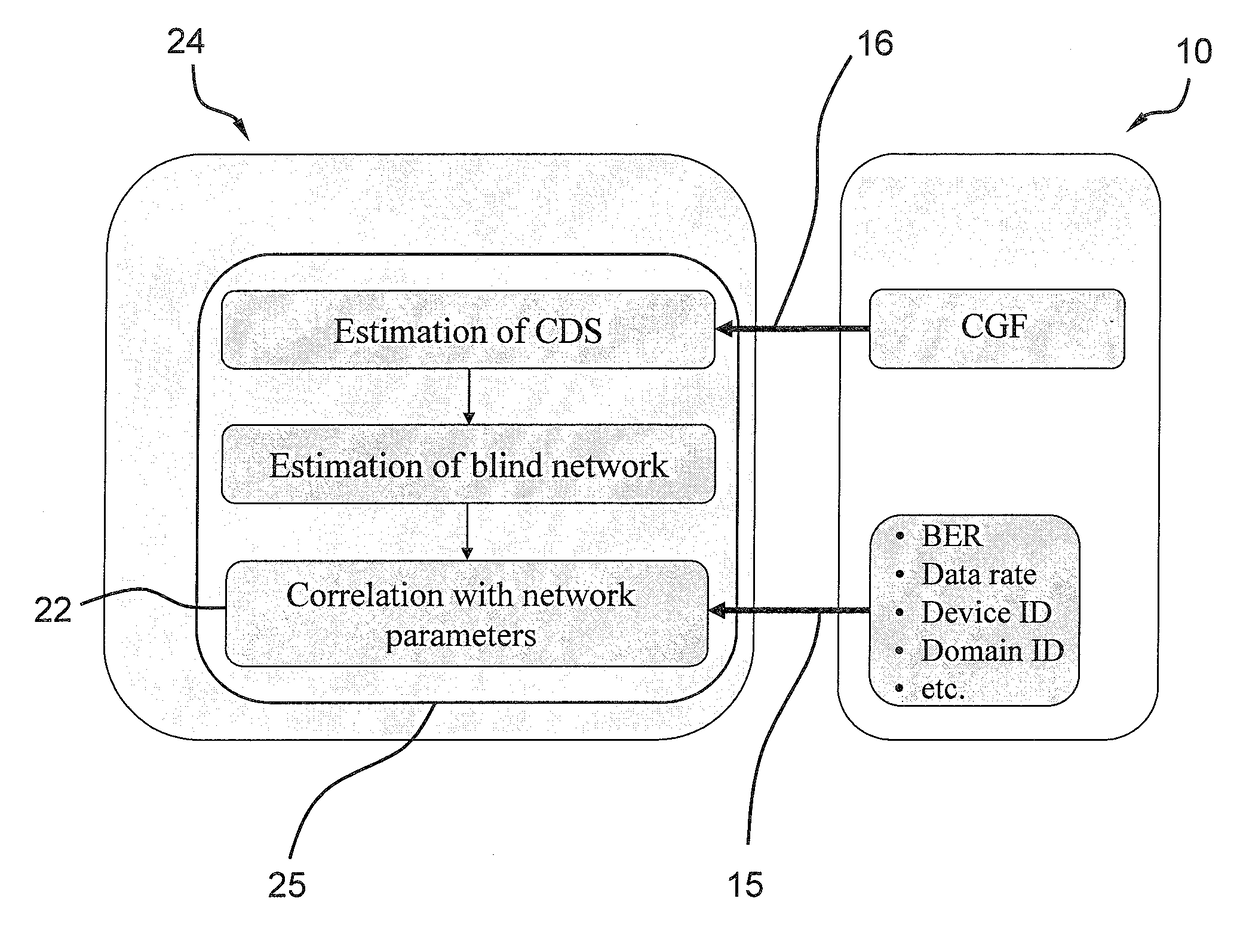
[0047]Remote from the home network 10 and connected to it via the residential gateway 23 is a management center 24 with a management center device 25 (FIG. 7). A software module is provided to carry out steps of the home network topology identification method as described in the following. The steps 15-22 (FIGS. 4, 5, and 7) are converted into a program code of the software module ...


PUM


Abstract

A home network topology identification method, wherein the home network (10; 11) has a plurality of network devices (27, 28, 29) with a residential gateway (23) among them, the method comprises the following steps:(1a) obtain at least one home network parameter from at least one of the network devices (27, 28, 29);(1b) obtain a network channel gain function (CGF) of the home network (10; 11) from one of the network devices (27, 28, 29);(1c) transform the channel gain function (CGF) into the time domain to obtain an equivalent estimated channel delay spread function (CDS);(1d) obtain an estimated blind network topology from the estimated channel delay spread function (CDS) and a propagation speed of the network; and(1e) correlate the estimated blind network topology with the at least one home network parameter to obtain at least one structural network topology parameter; anda management center device (25) that is remote from a home network (10; 11) having a plurality of network devices (27, 28, 29) with a residential gateway (23) among them, wherein the management center device (25) is provided to carry out steps (1a) to (1e) of the method.

Description

[0001]The invention relates to a home network topology identification method and a management center device provided to carry out the method.BACKGROUND ART[0002]International Telecommunication Union (ITU) standard “G.hn” was defined to enable broadband data communication required by in-house broadband applications. In G.hn, different domains are available for in-house network access by different media, like copper twisted-pairs, coaxial cables, and power line cables.[0003]To date, troubleshooting and diagnostics of in-house networks, also known as home networks, from a remote location outside of the network is a challenging task. In particular, the identification of size and structure of a home network is challenging due to a potential large number of branches and terminations within the home network.[0004]To further illustrate the problem, examples of home networks with relatively simple structures and one branch and three branches, respectively, are shown in FIG. 1. Channel gain f...

Claims


Application Information

Patent Timeline
Patent Type & Authority Patents(United States)
IPC IPC(8): H04L12/24H04L12/28H04B3/54H04L12/751H04L45/02
CPCH04L41/12H04B3/542H04L12/2807H04B2203/5408H04B2203/5416H04B2203/5445H04L45/02Y04S40/164Y04S40/00H04L41/046H04L25/0222
Inventor GACANIN, HARIS
Owner WSOU INVESTMENTS LLC
Features
  • R&D
  • Intellectual Property
  • Life Sciences
  • Materials
  • Tech Scout
  • Unparalleled Data Quality
  • Higher Quality Content
  • 60% Fewer Hallucinations
Learn More