Check patentability & draft patents in minutes with Patsnap Eureka AI!

Raintight compression connector and raintight compression coupler for securing electrical metallic tubing or rigid metallic conduit

a technology of connectors and connectors, applied in the direction of mechanical equipment, electrical equipment, engine seals, etc., can solve the problems that existing connectors and couplers may have difficulty maintaining a raintight connection, and achieve the effect of improving the raintight compression connector or coupler

Active Publication Date: 2017-10-10
BRIDGEPORT FITTINGS LLC
View PDF78 Cites 9 Cited by
  • Summary
  • Abstract
  • Description
  • Claims
  • Application Information

AI Technical Summary

Benefits of technology

[0006]EMT or RMC, as well as a skewed terminating face of the EMT or RMC (not at right angles to the longitudinal axis of the EMC or RMC) and thereby provides an improved raintight compression connector or coupler.

Problems solved by technology

It has been observed that existing connectors and couplers may have difficulty maintaining a raintight connection, due to sealing surface imperfections of the EMT or RMC outside diameters, especially with larger diameter trade sizes.

Method used


Image

  • Raintight compression connector and raintight compression coupler for securing electrical metallic tubing or rigid metallic conduit
  • Raintight compression connector and raintight compression coupler for securing electrical metallic tubing or rigid metallic conduit
  • Raintight compression connector and raintight compression coupler for securing electrical metallic tubing or rigid metallic conduit

Examples


Embodiment Construction

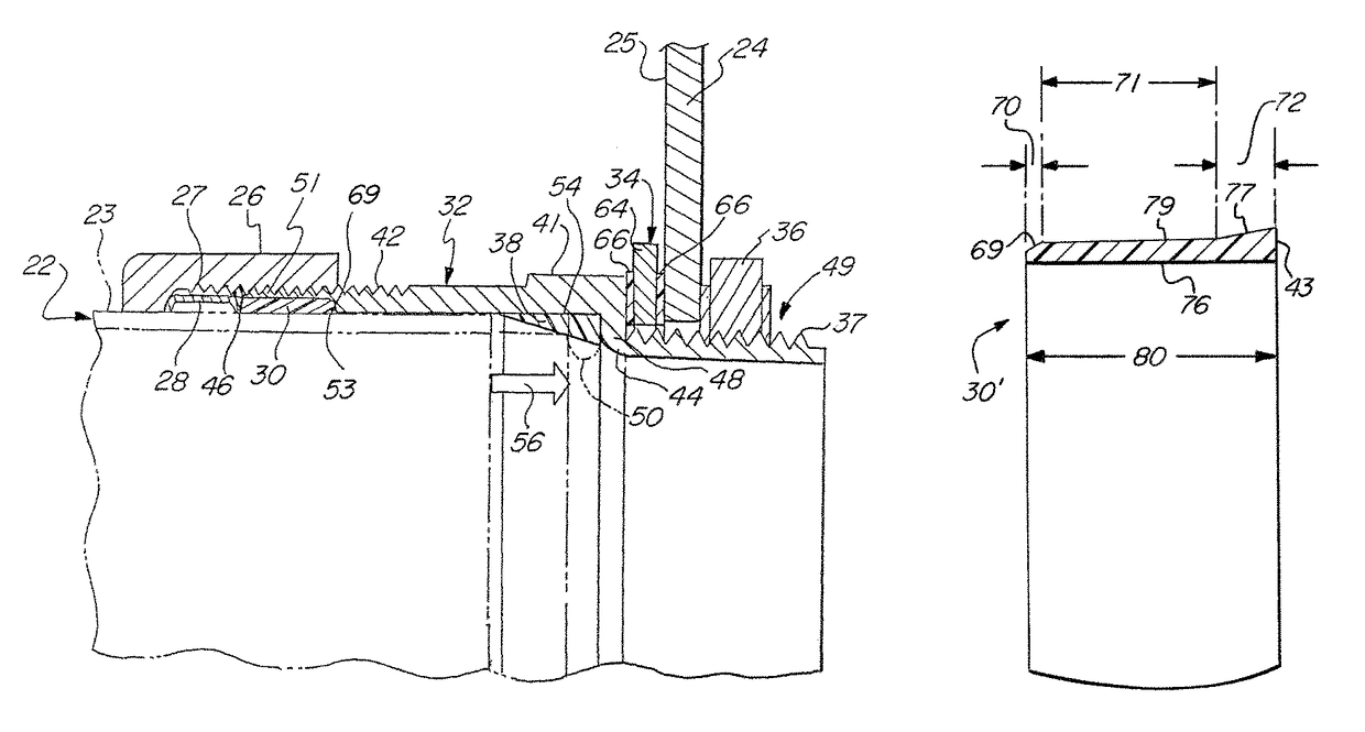
[0055]The present invention is an improved upper sealing ring 30′ forming part of a raintight compression connector 20 or a raintight compression coupler 20′ as discussed below.

[0056]As seen in FIG. 1, an embodiment of a raintight compression connector 20 according to the present invention is configured for receipt of an electrical metallic tubing or rigid metallic conduit (EMT or RMC) 22 (collectively referred to as conduit) so as to form a raintight seal between the EMT or RMC and an electrical enclosure 24 to which the compression connector is attached through a knockout hole (see, for example, knockout hole 39). Such a raintight compression connector is typically used in applications where the electrical enclosure 24 is exposed to water, such as an outdoor environment where rain is present from time to time. It is known in the art that RMC is similar to EMC, but has a greater wall thickness and is therefore typically used in what are considered in the electrical contractor indus...


PUM


Abstract

A raintight compression connector has a connector body with first and second portions and a bore extending therethrough for connection to a conduit. An upper sealing ring is dimensioned to contact the connector body to make sealing contact with a conduit. The upper sealing ring has first, second and third regions. The first region has a first sloping surface to contact a recess shoulder in the connector body and the third region has a third sloping surface to contact an inner surface of the connector body. Specific slopes for these sloping surfaces are disclosed. The upper sealing ring can also be used in a raintight compression coupler.

Description

CROSS REFERENCE TO RELATED APPLICATIONS[0001]This application claims priority under 35 USC §119 to U.S. Provisional Patent Application No. 62 / 142,150 filed on Apr. 2, 2015, whose entire contents are hereby incorporated by reference.[0002]This application also claims priority to U.S. Utility patent application Ser. No. 14 / 068,663filed on Oct. 31, 2013, now U.S. Pat. No. 9,343,883, whose contents are also hereby incorporated by reference.FIELD OF THE INVENTION[0003]This invention is directed to an improved raintight compression connector for securing electrical metallic tubing (EMT), or rigid metallic conduit (RMC), to an electrical enclosure and to a raintight compression coupler for securing two EMT's or RMC's to each other. The connector and coupler are sometimes collectively referred to herein as an electrical fitting or fitting. The improvement is specifically with respect to the upper sealing ring associated with the fitting.BACKGROUND OF THE INVENTION[0004]Various types of rain...

Claims


Application Information

Patent Timeline
Patent Type & Authority Patents(United States)
IPC IPC(8): H02G3/06F16J15/02F16J15/10
CPCH02G3/0616F16J15/10F16J15/028
Inventor DECESARE, CHRISTOPHER W.SMITH, LAWRENCE J.
Owner BRIDGEPORT FITTINGS LLC
Features
  • R&D
  • Intellectual Property
  • Life Sciences
  • Materials
  • Tech Scout
  • Unparalleled Data Quality
  • Higher Quality Content
  • 60% Fewer Hallucinations
Learn More