Supercharge Your Innovation With Domain-Expert AI Agents!

Transmitter/receiver apparatus, transmitter apparatus and transmitting/receiving method

a transmitter and receiver technology, applied in the field of transmitter/receiver apparatus, transmitter apparatus and transmitting/receiving method, can solve the problems of inability to achieve perfect grounding of diodes at high frequency bands, and inability to achieve perfect isolation, etc., to achieve the effect of reducing the electric power consumption of the apparatus, simplifying the configuration of the transmit/receive switch unit, and keeping the electric power efficiency high

Active Publication Date: 2017-12-05
NEC CORP
View PDF11 Cites 2 Cited by
  • Summary
  • Abstract
  • Description
  • Claims
  • Application Information

AI Technical Summary

Benefits of technology

This configuration significantly reduces power leakage, simplifies the transmit / receive switch unit, and enhances power efficiency by eliminating electric power loss, allowing for quick switching between transmitting and receiving operations.

Problems solved by technology

However, in the examples shown in FIG. 13 and FIG. 14, to make the diode 21 grounded is actually not perfect at a high frequency band.
Therefore, impedance of the transmit / receive switch unit 2 is not infinite, and consequently perfect isolation cannot be carried out.
As a result, a finite electric power loss exists.
Since, in general, PA is one of blocks which consume electric power most among wireless apparatuses, an electric power loss of a PA output causes increase of electric power consumption of the whole apparatus even if the electric power loss of the PA output is minute.

Method used


Image

  • Transmitter/receiver apparatus, transmitter apparatus and transmitting/receiving method
  • Transmitter/receiver apparatus, transmitter apparatus and transmitting/receiving method
  • Transmitter/receiver apparatus, transmitter apparatus and transmitting/receiving method

Examples


first exemplary embodiment

[0079][Configuration of First Exemplary Embodiment]

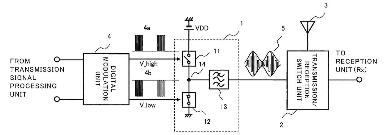
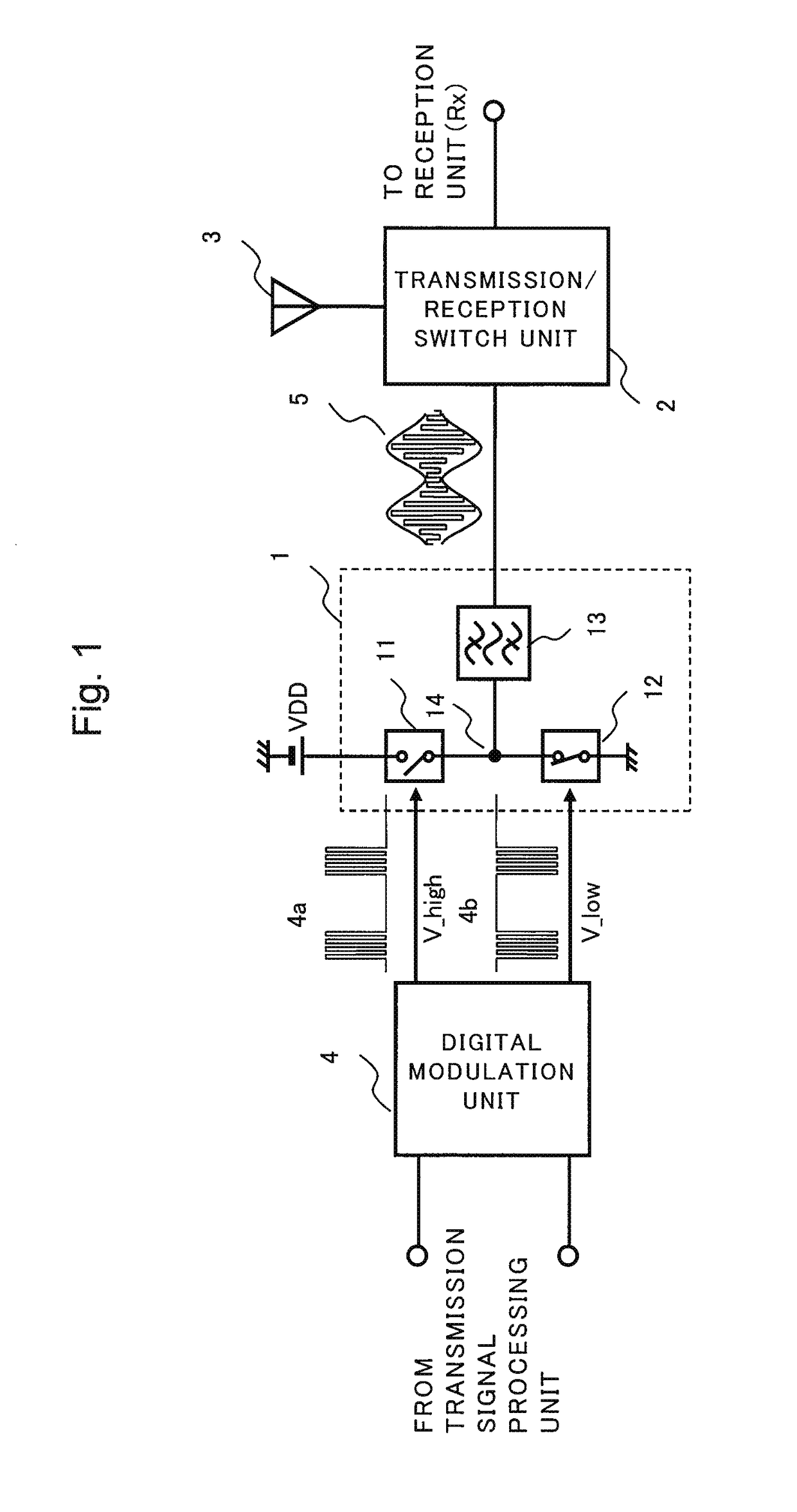
[0080]FIG. 1 is a block diagram showing a configuration of a wireless communication apparatus that is a first exemplary embodiment of the present invention.

[0081]The wireless communication apparatus of the present exemplary embodiment includes a switching amplification unit 1, a transmit / receive switch unit 2, an antenna 3 and a digital modulation unit 4.

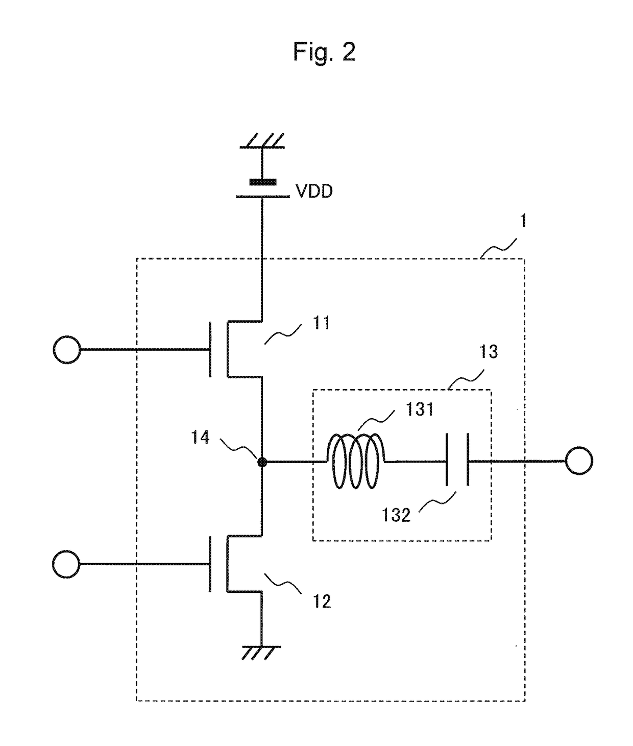
[0082]The switching amplification unit 1 includes two switching elements 11 and 12 that are arranged in a form of series-connection and connected between an electric power supply and the ground, and a filter 13.

[0083]The digital modulation unit 4 receives input of data provided by a transmitting signal processing unit (not shown in the drawing), and outputs switching amplifier control signals 4a and 4b that are complementary two-level pulse signals including information of the inputted data as time information. The switching amplifier control signals 4a and 4b are inputted into the ...

second exemplary embodiment

[0105][Configuration of Second Exemplary Embodiment]

[0106]FIG. 7 is a block diagram showing a configuration of a wireless communication apparatus of a second exemplary embodiment of the present invention. In the case of the wireless communication apparatus of the present exemplary embodiment, the switching amplification unit 1 is directly connected with the antenna 3.

[0107]Similarly to the wireless communication apparatus of the first exemplary embodiment, the wireless communication apparatus of the present exemplary embodiment includes the switching amplification unit 1, the transmit / receive switch unit 2, the antenna 3 and the digital modulation unit 4.

[0108]The switching amplification unit 1 includes the two switching elements 11 and 12 that are arranged in a form of series-connection and connected between an electric power supply and the ground and includes the filter 13.

[0109]The digital modulation unit 4 receives input of data provided by a transmitting signal processing unit ...

third exemplary embodiment

[0133][Configuration of Third Exemplary Embodiment]

[0134]FIG. 11 is a block diagram showing a configuration of a wireless communication apparatus of a third exemplary embodiment of the present invention. In the case of the wireless communication apparatus of the present exemplary embodiment, the switching amplification unit 1 is connected with the antenna 3 through a transmission line 27.

[0135]Similarly to the wireless communication apparatuses of the first and the second exemplary embodiments, the wireless communication apparatus of the present exemplary embodiment includes the switching amplification unit 1, the transmit / receive switch unit 2, the antenna 3, the digital modulation unit 4, the filter 13 and the switching elements 11 and 12.

[0136]The switching amplification unit 1 includes two switching elements 11 and 12 that are arranged in a form of series-connection and connected between the electric power supply and the ground.

[0137]The digital modulation unit 4 receives input ...


PUM


Abstract

A transmitter / receiver apparatus including: a transmitter / receiver terminal; a switching amplifier that includes a low-side switching element connected between a ground terminal and a pulse output terminal and a high-side switching element connected between the pulse output terminal and a power supply terminal and that outputs a pulse signal from the pulse output terminal; a filter that passes therethrough and outputs as a transmitted signal a predetermined frequency component of the pulse signal from a transmitter terminal; and a transmit / receive switch unit that switches the connection status between the transmitter / receiver terminal and the transmitter terminal and also switches the connection status between the transmitter / receiver terminal and a receiver terminal. During receiving, on the basis of the connection status between the transmitter / receiver terminal and the transmitter terminal, the low-side and high-side switching elements are fixed to conductive and non-conductive states, respectively, to non-conductive and conductive states, respectively, or both to non-conductive states.

Description

CROSS REFERENCE TO RELATED APPLICATIONS[0001]This application is a National Stage of International Application No. PCT / JP2014 / 005216 filed Oct. 15, 2014, claiming priority based on Japanese Patent Application No. 2013-218937, filed Oct. 22, 2013, the contents of which are incorporated herein by reference in their entirety.TECHNICAL FIELD[0002]The present invention relates to a transmitter / receiver apparatus, a transmitter apparatus and a transmitting / receiving method, and particularly relates to transmitter / receiver apparatuses, transmitter apparatuses and transmitting / receiving methods that can switch between a state for transmitting and a state for receiving.BACKGROUND ART[0003]In wireless communication apparatuses based on a Time Division Duplex (hereinafter, abbreviated as ‘TDD’) method, a communication time is divided by a constant time (transmitting period and receiving period), and transmitting and receiving are alternately carried out during the transmitting period and the r...

Claims


Application Information

Patent Timeline
Patent Type & Authority Patents(United States)
IPC IPC(8): H04L5/16H04B1/44H03F3/217H03F3/195H03F3/213H04B1/3827H03F3/24H04L27/36H04L27/38
CPCH03F3/213H03F3/217H03F3/2171H03F3/2173H04B1/3833H04L27/36H04L27/38H03F3/245H04B1/44H03F3/195H03F2200/451H03F2200/171H03F2200/294H03F2200/331
Inventor KUNIHIRO, KAZUAKIHORI, SHINICHI
Owner NEC CORP
Features
  • R&D
  • Intellectual Property
  • Life Sciences
  • Materials
  • Tech Scout
  • Unparalleled Data Quality
  • Higher Quality Content
  • 60% Fewer Hallucinations
Learn More