Cutting apparatus and printing apparatus
a cutting apparatus and printing technology, applied in the direction of printing, metal working apparatus, other printing apparatus, etc., can solve the problems of inconvenient cutting, significant wear of cutting edges, and shortening the life of the blades, so as to enhance cutting performance and suppress the wear of cutting edges
- Summary
- Abstract
- Description
- Claims
- Application Information
AI Technical Summary
Benefits of technology
Problems solved by technology
Method used
Image

Examples
first embodiment
[0035]A first embodiment of the present invention will be described with reference to the drawings. The same reference numerals denote the same or corresponding components throughout the drawings.
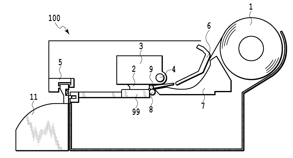
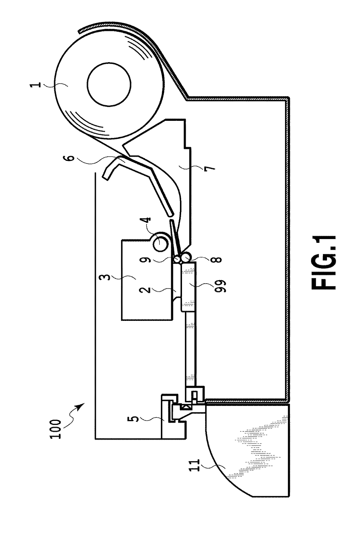
[0036]FIG. 1 is a schematic sectional view depicting an ink jet printing apparatus according to the first embodiment of the present invention. With reference to FIG. 1, a general configuration of the ink jet printing apparatus according to the present embodiment will be described. Rolled paper 1 held in an ink jet printing apparatus 100 is fed downstream through a conveying path including an upper guide 6 and a lower guide 7. When a leading end of the rolled paper 1 reaches a nip portion between a conveying roller 8 and a pinch roller 9, the rolled paper 1 is sandwiched between the conveying roller 8 and the pinch roller 9 and conveyed onto a platen 99 (image printing section) arranged opposite to a print head 2.
[0037]The image printing section includes the print head 2, a carriage 3 on whi...
second embodiment
[0105]A second embodiment of the present invention will be described with reference to the drawings. A basic configuration of the present embodiment is similar to the basic configuration of the first embodiment, and only a characteristic part of the configuration will be described below.
[0106]The second embodiment of the present invention will be described with reference to FIG. 12, FIG. 13, FIG. 14, FIG. 15A, and FIG. 15B. A variation of the pressure spring 25 serving as a pressing force changing device and a periphery of the pressure spring 25 are illustrated. However, the same components as those of the first embodiment are denoted by the same reference numerals and will not be described below.
[0107]FIG. 12 is a schematic sectional view of the cutter unit 12 of the present embodiment as seen from above. The upper movable blade 13a in the cutter unit 12 of the present embodiment is pressed against the lower movable blade 13b by two springs, a low-pressing-force spring 26a and a hi...
third embodiment
[0118]A third embodiment will be described below with reference to the drawings. A basic configuration of the present embodiment is similar to the basic configuration of the first embodiment, and only a characteristic part of the configuration will be described below. In the present embodiment, the sliding distance of the pressing member 28, which is the pressing force changing device for the start of the cutting, is freely switched to change the pressing force exerted at the start of the cutting, in stages. The same components as those of the first and second embodiments are denoted by the same reference numerals and will not be described below.
[0119]FIG. 16A and FIG. 16B are diagrams depicting the pressing force changing device of the present embodiment. FIG. 16A is a schematic sectional view of the cutter unit exerting a pressing force at the first stage. FIG. 16B is a side view of a cam.
[0120]In the present embodiment, the pressing force exerted on the lower movable blade 13b by...
PUM
 Abstract
Description
Claims
Application Information
 - R&D
- Intellectual Property
- Life Sciences
- Materials
- Tech Scout
- Unparalleled Data Quality
- Higher Quality Content
- 60% Fewer Hallucinations
Browse by: Latest US Patents, China's latest patents, Technical Efficacy Thesaurus, Application Domain, Technology Topic, Popular Technical Reports.
© 2025 PatSnap. All rights reserved.Legal|Privacy policy|Modern Slavery Act Transparency Statement|Sitemap|About US| Contact US: help@patsnap.com