Supercharge Your Innovation With Domain-Expert AI Agents!

Drive assembly for a motorized roller tube system

a technology of motorized roller tube and drive assembly, which is applied in the direction of doors/windows, screens, constructions, etc., can solve the problem of inefficient motor drive at relatively slow motor speed

Active Publication Date: 2018-02-13
LUTRON TECH CO LLC
View PDF46 Cites 6 Cited by
  • Summary
  • Abstract
  • Description
  • Claims
  • Application Information

AI Technical Summary

Benefits of technology

The patent describes a motor that uses a gear assembly with planetary spur gears and is designed to make minimal noise during movement. The motor produces a sound pressure level of between 40 dBA and 44 dBA when the roller tube is moving. This level of sound is considered to be pleasant and not distracting.

Problems solved by technology

The drive assembly is configured such that the motor is driven inefficiently at relatively slow motor speeds.

Method used


Image

  • Drive assembly for a motorized roller tube system
  • Drive assembly for a motorized roller tube system
  • Drive assembly for a motorized roller tube system

Examples


Embodiment Construction

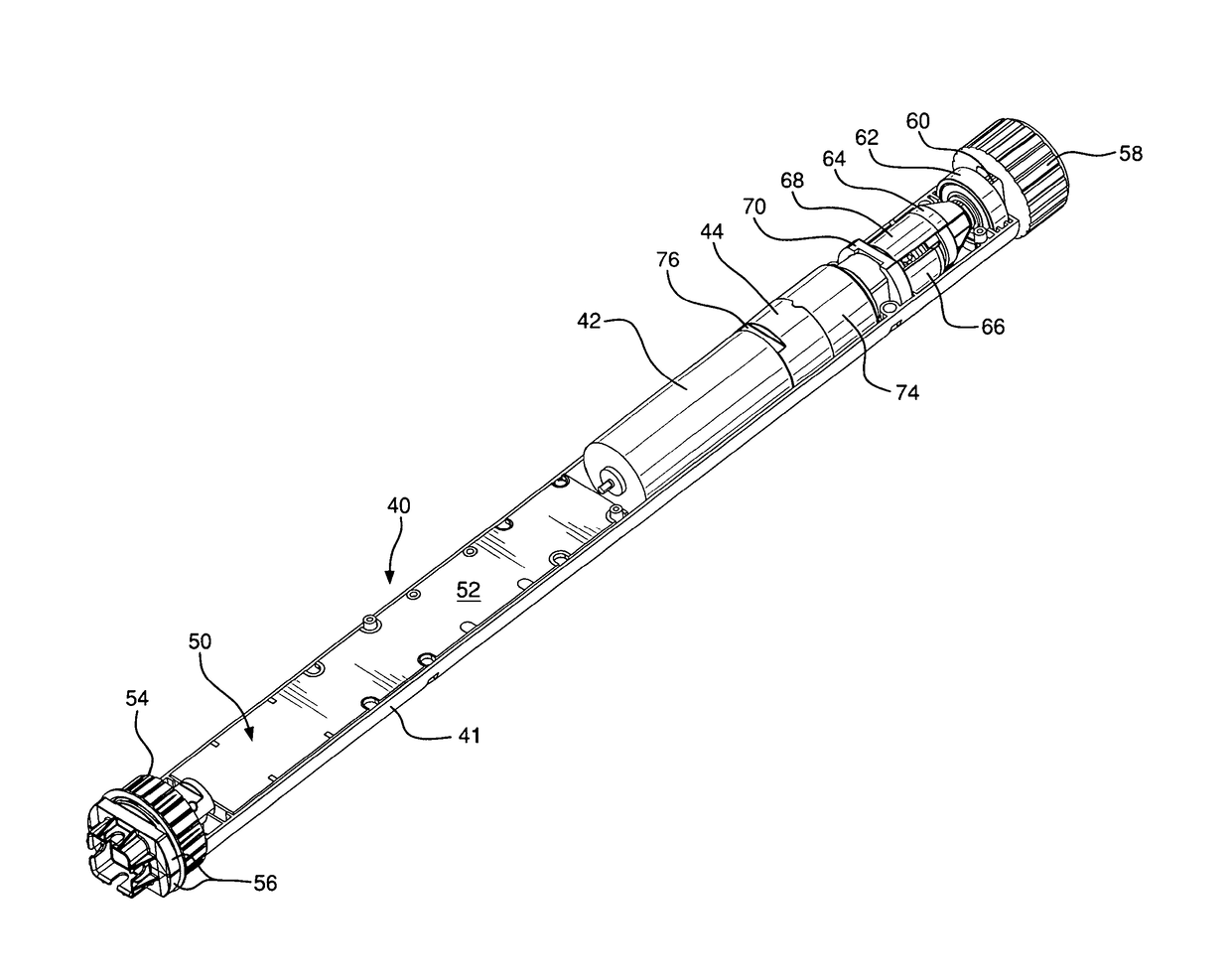
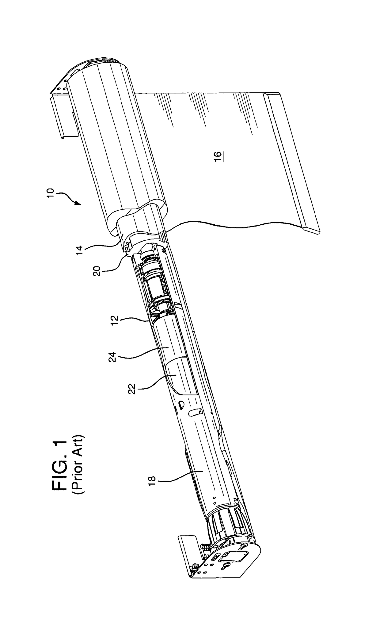
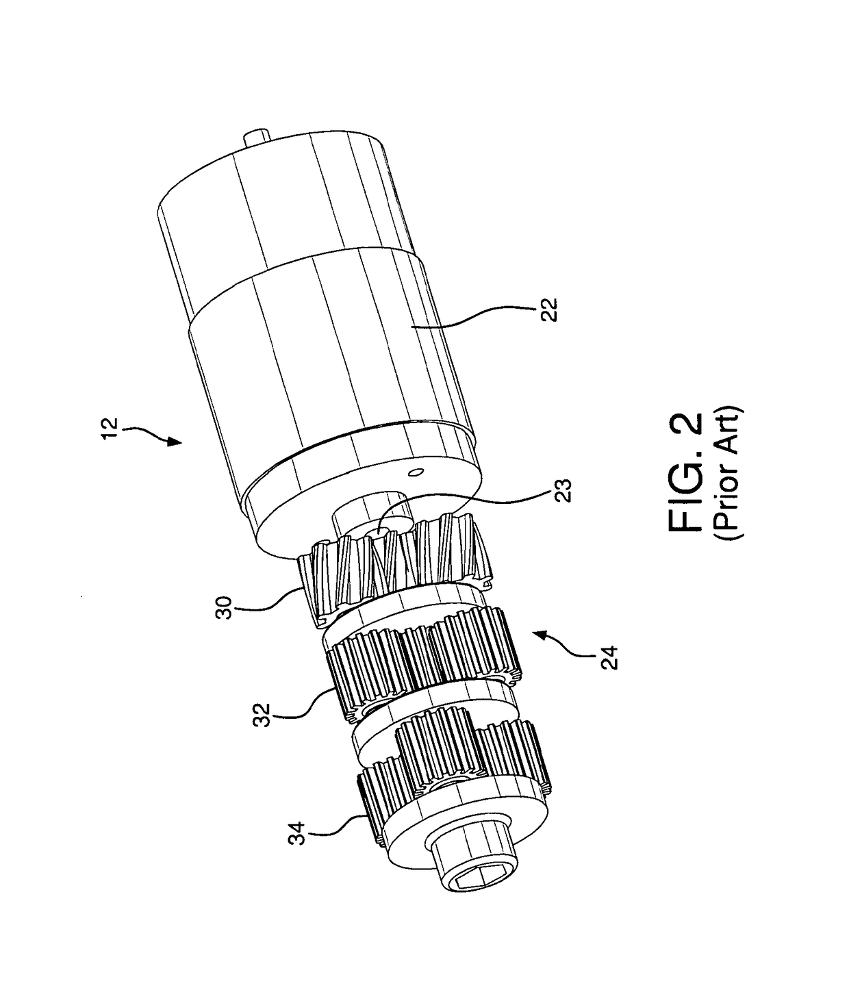
[0023]Referring to the drawings, where like numerals identify like elements, there is shown in FIGS. 4 through 6 a roller tube drive assembly 40 according to the present invention including a motor 42 and a gear assembly 44 contained within an elongated housing 41. The drive assembly 40 of the present invention is adapted for receipt within a roller tube, such as the tube 14 of FIG. 1, to engage an inner surface of the roller tube for rotating the tube to wind or unwind a flexible member, such as a window shade fabric. The receipt and engagement of the drive assembly 40 is similar to that described above for the prior drive assembly 12. As described below in greater detail, however, the drive assembly 40 of the present invention is configured in a novel manner providing for reduction in roller tube diameter for driving a given applied load or, alternatively, driving a large applied load for a given roller tube diameter. Also, the novel configuration generates limited noise for relat...


PUM


Abstract

A motorized roller tube for reeling and unreeling a flexible member between fully open and fully closed conditions operates with minimized sound level. A variable controller energizes a motor with a controllable RPM driving a gear reduction assembly. The motor has a speed versus torque characteristic which extends linearly from a high maximum RPM and low minimum torque, to a low minimum RPM and high maximum torque, and having a peak efficiency at a given RPM. The motor moves the flexible member between its fully open and fully closed positions at a motor speed less than the given peak efficiency RPM and less than 50% of its high maximum RPM, and at a motor efficiency which is less than 25% of the peak efficiency whereby the motor is intentionally operated in a high torque and low efficiency manner.

Description

CROSS-REFERENCE TO RELATED APPLICATION[0001]The present application is a continuation under 37 C.F.R. §1.53(b) of prior U.S. Ser. No. 11 / 096,783. filed Apr. 1, 2005 in the names of Jason O. Adams; Thomas W. Brenner; Brandon J. Detmer; Robert C. Newman, Jr.; and Joel Spira entitled DRIVE ASSEMBLY FOR A MOTORIZED ROLLER TUBE SYSTEM which is related to co-pending U.S. Ser. No. 11 / 096,784. filed Apr. 1, 2005 in the name of Robert C. Newman, Jr. entitled MOTORIZED ROLLER TUBE SYSTEM HAVING DUAL-MODE OPERATION the co-pending application is incorporated herein by reference in its entirety.FIELD OF THE INVENTION[0002]The present invention relates to motorized roller tube systems, used for winding flexible members such as shades, screens and the like, and more particularly to a drive assembly for a motorized roller tube system.BRIEF DESCRIPTION OF THE DRAWINGS[0003]FIG. 1 is a perspective view of a motorized roller tube system including a prior drive assembly.[0004]FIG. 2 shows the motor and...

Claims


Application Information

Patent Timeline
Patent Type & Authority Patents(United States)
IPC IPC(8): E06B9/72
CPCE06B9/72E06B2009/725
Inventor ADAMS, JASON O.BRENNER, THOMAS W.DETMER, BRANDON J.NEWMAN, JR., ROBERT C.SPIRA, JOEL S.
Owner LUTRON TECH CO LLC
Features
  • R&D
  • Intellectual Property
  • Life Sciences
  • Materials
  • Tech Scout
  • Unparalleled Data Quality
  • Higher Quality Content
  • 60% Fewer Hallucinations
Learn More