Check patentability & draft patents in minutes with Patsnap Eureka AI!

Swash plate type variable displacement compressor

a variable displacement compressor and compressor technology, applied in the direction of positive displacement liquid engine, pump components, pulse equalisation, etc., can solve the problems of compressor actuator pulsation of discharge refrigerant, unstable inclination angle, and difficult operation at a suitable displacement, so as to reduce the pulsation of refrigerant

Active Publication Date: 2018-02-27
TOYOTA IND CORP
View PDF63 Cites 1 Cited by
  • Summary
  • Abstract
  • Description
  • Claims
  • Application Information

AI Technical Summary

Benefits of technology

The present invention provides a swash plate type variable displacement compressor with a control mechanism that can adjust the inclination angle of the swash plate for changing the displacement of the compressor. The actuator changes the inclination angle of the swash plate by controlling a fixed body and a movable body. The control mechanism includes a control passage and a control valve to adjust the pressure in the control pressure chamber for moving the movable body. The refrigerant in the discharge chamber flows into the control pressure chamber via the pressure regulation chamber to function as a muffler to reduce pulsation of the refrigerant. The technical effects of the invention include improved efficiency and control of the compressor for better performance and reliability.

Problems solved by technology

Thus, the actuator of this compressor is susceptible to pulsation of the discharge refrigerant.
This makes the inclination angle unstable and makes the compressor hard to operate at a suitable displacement in accordance with the operating condition of, for example, a vehicle to which the compressor is mounted.

Method used


Image

  • Swash plate type variable displacement compressor
  • Swash plate type variable displacement compressor
  • Swash plate type variable displacement compressor

Examples


first embodiment

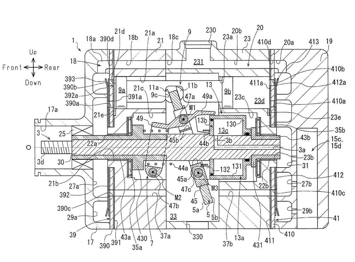
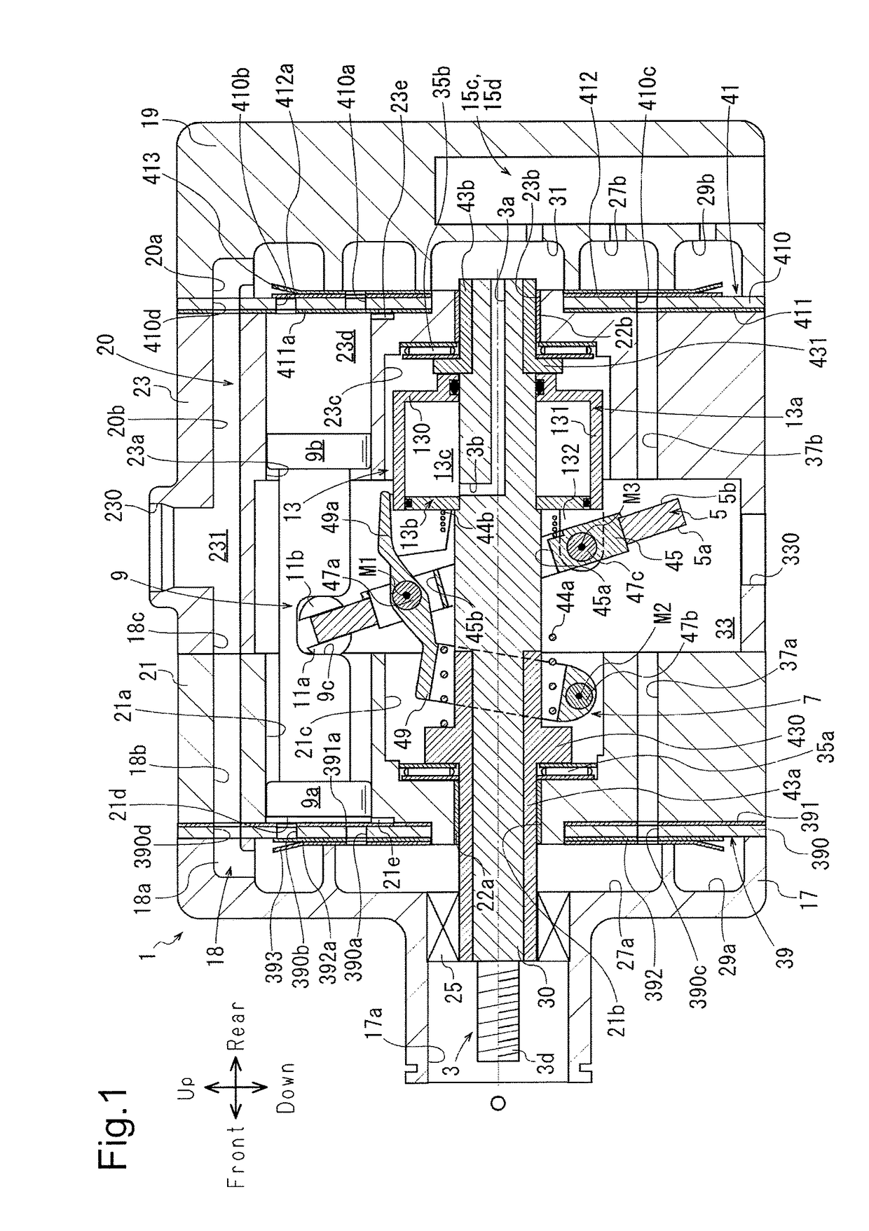
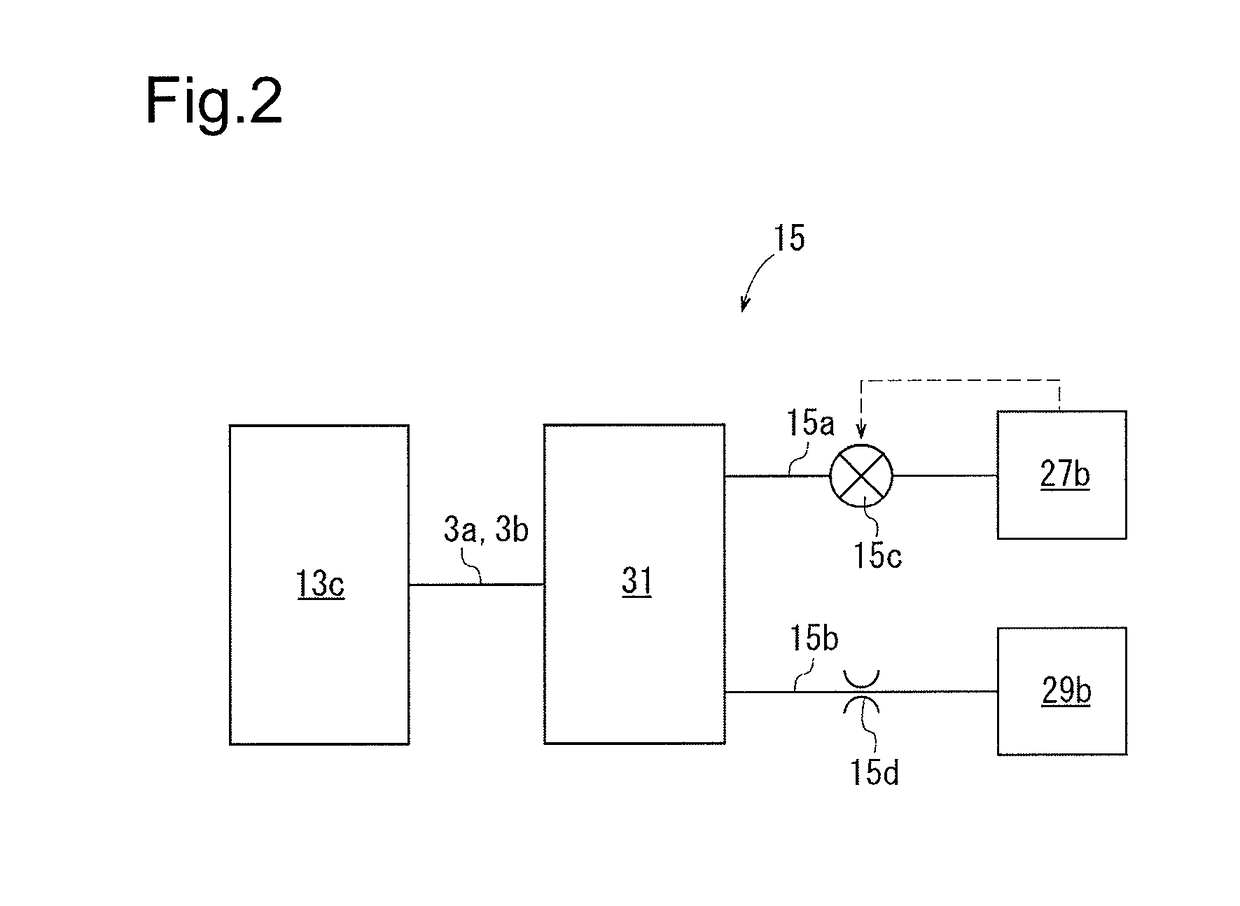
[0021]As shown in FIG. 1, the compressor according to the first embodiment includes a housing 1, a drive shaft 3, a swash plate 5, a link mechanism 7, pistons 9, pairs of shoes 11a, 11b, an actuator 13, and a control mechanism 15, which is illustrated in FIG. 2.

[0022]As shown in FIG. 1, the housing 1 has a front housing member 17 at a front position in the compressor, a rear housing member 19 at a rear position in the compressor, first and second cylinder blocks 21, 23, which are arranged between the front housing member 17 and the rear housing member 19, and first and second valve forming plates 39, 41.

[0023]The front housing member 17 has a boss 17a, which projects forward. The boss 17a accommodates a shaft sealing device 25. A first suction chamber 27a and a first discharge chamber 29a are formed in the front housing member 17. The first suction chamber 27a is located radially inward in the front housing member 17. The first discharge chamber 29a is formed into an annular shape a...

second embodiment

[0095]As shown in FIG. 4, a compressor according to a second embodiment includes a housing 201, a drive shaft 203, a swash plate 205, a link mechanism 207, pistons 209, pairs of shoes 211a, 211b, an actuator 213, and a control mechanism 16, which is illustrated in FIG. 5.

[0096]As shown in FIG. 4, the housing 201 has a front housing member 217 at a front position in the compressor, a rear housing member 219 at a rear position in the compressor, and a cylinder block 221 and a valve forming plate 223, which are arranged between the front housing member 217 and the rear housing member 219.

[0097]The front housing member 217 includes a front wall 217a, which extends in the vertical direction of the compressor on the front side, and a circumferential wall 217b, which is integrally formed with the front wall 217a and extends rearward from the front of the compressor. The front housing member 217 is formed into a substantially cylindrical cup shape with the front wall 217a and the circumfere...


PUM


Abstract

A swash plate type variable displacement compressor includes a housing in which a suction chamber, a discharge chamber, a swash plate chamber, and a cylinder bore are formed, a drive shaft, a swash plate, an actuator, and a control mechanism that controls the actuator. A pressure regulation chamber is formed in the housing. The actuator includes a control pressure chamber. The control mechanism includes a control passage that connects together the discharge chamber, the pressure regulation chamber, and the control pressure chamber, and a control valve that, by adjusting the degree of opening of the control passage, changes the pressure in the control pressure chamber to allow the movable body to move. Refrigerant in the discharge chamber flows into the control pressure chamber via the pressure regulation chamber. The pressure regulation chamber functions as a muffler that reduces the pulsation of the refrigerant.

Description

FIELD OF THE INVENTION[0001]The present invention relates to a swash plate type variable displacement compressor.BACKGROUND OF THE INVENTION[0002]Patent Document 1 discloses a conventional swash plate type variable displacement compressor (hereinafter referred to as a compressor). This compressor includes a front housing member, a cylinder block, and a rear housing member, which form a housing. The front housing member and the rear housing member each include a suction chamber and a discharge chamber. The rear housing member also includes a control pressure chamber.[0003]The cylinder block includes a swash plate chamber, a plurality of cylinder bores, and a main shaft through hole. Each cylinder bore includes a first cylinder bore formed in the rear part of the cylinder block and a second cylinder bore formed in the front part of the cylinder block. The main shaft through hole is formed in the rear part of the cylinder block and communicates with the swash plate chamber and the cont...

Claims


Application Information

Patent Timeline
Patent Type & Authority Patents(United States)
IPC IPC(8): F04B27/18F04B27/10F04B27/12F04B11/00
CPCF04B27/18F04B27/1054F04B27/12F04B2027/1831F04B11/0091F04B2027/1818
Inventor NAKAIMA, HIROYUKIYAMAMOTO, SHINYASUZUKI, TAKAHIROOTA, MASAKIHONDA, KAZUNARINISHII, KEIYAMAZAKI, YUSUKE
Owner TOYOTA IND CORP
Features
  • R&D
  • Intellectual Property
  • Life Sciences
  • Materials
  • Tech Scout
  • Unparalleled Data Quality
  • Higher Quality Content
  • 60% Fewer Hallucinations
Learn More