Radio sensing device and radar system
a radio sensing device and radar technology, applied in the direction of measuring devices, using reradiation, instruments, etc., can solve the problems of unfavorable safety, increased costs, and unnecessary addition of new hardware, so as to reduce the probability of wave interference, increase all costs, and minimize the effect of radio interference with adjacent similar devices
- Summary
- Abstract
- Description
- Claims
- Application Information
AI Technical Summary
Benefits of technology
Problems solved by technology
Method used
Image


Examples
first embodiment
[0045]A first embodiment of the present invention will be described below with reference to FIGS. 1 to 4.
[0046]In this embodiment, two vehicles will be exemplified.
[0047]As shown in FIG. 3A, in the past, antennas are switched in a fixed order. In the drawing, reference symbols and numerals “T”, “Trand”, and “1, 2, 3, or 4” understandably represent a measurement cycle, a time required for making a circle of random numbers, and a selected measurement antenna, respectively. In the embodiment, the measurement cycle “T” is not changed. Measurement antennas are switched as shown in FIG. 3B when Trand=T, and are switched as shown in FIG. 3C when Trand=2T.
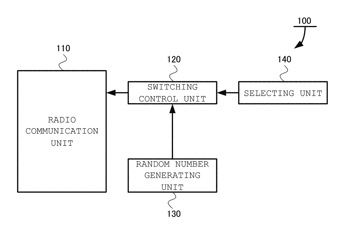
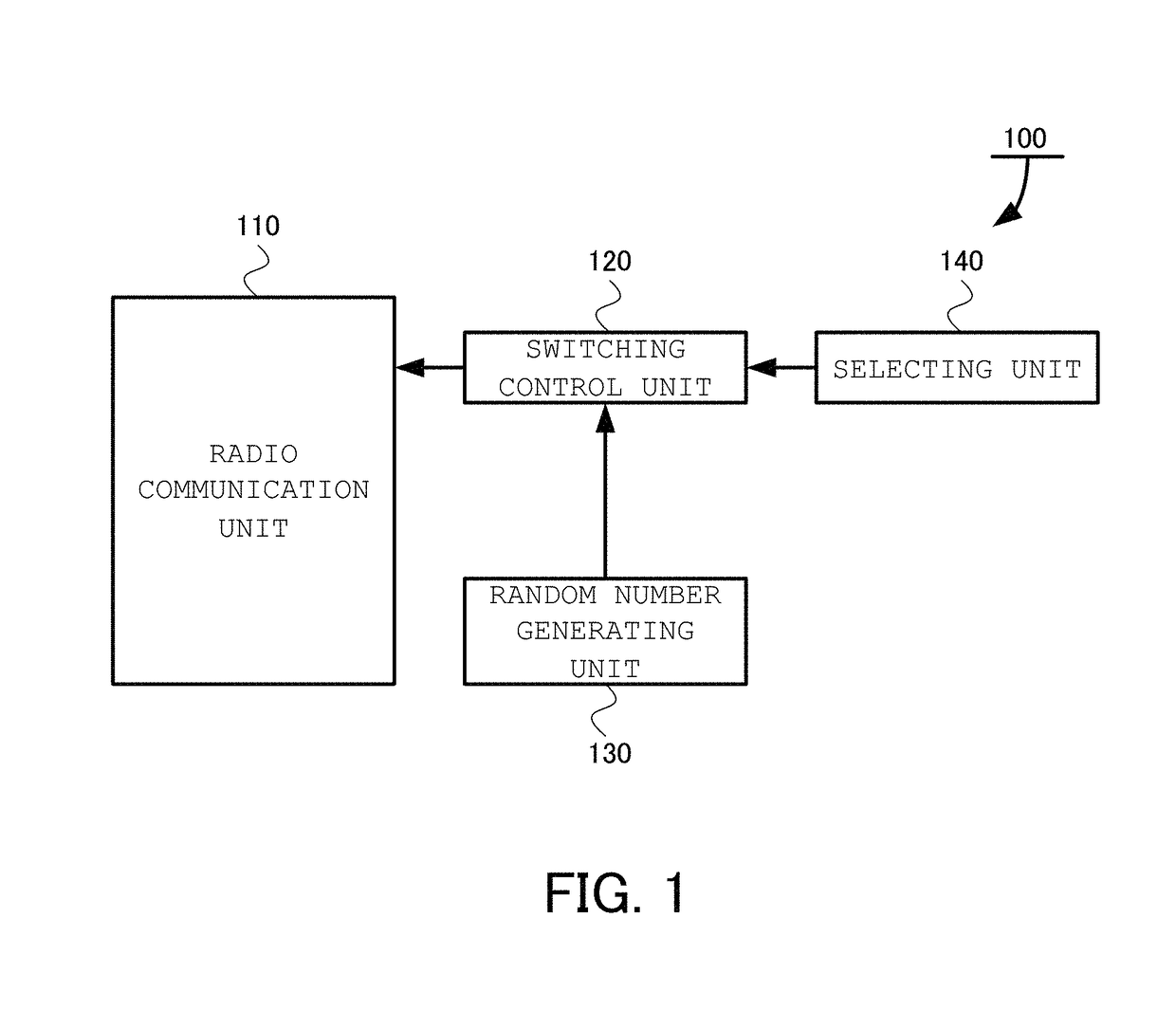
[0048]A radio sensing device 100 according to the present invention, as shown in FIG. 1, includes a radio communication unit 110, a switching control unit 120, a random number generating unit 130, and a selecting unit 140.
[0049]The radio communication unit 110 is a unit to transmit and receive radio waves by using a plurality of antennas. ...
second embodiment
[0059]A second embodiment of the present invention will be described below with reference to FIG. 5 and FIG. 6.
[0060]In the first embodiment, a scanning order of beam directions is the effect of the embodiment, and a unit for scanning the beam directions is not limited to a specific unit. In FIG. 4, a so-called switch changeover scheme which selects a plurality of antennas such that the antennas are arranged in a circular shape or a spherical-shell shape is described. However, as the unit for scanning beam directions, a mechanical scanning scheme or the like known as another unit may be used. More specifically, as shown in FIG. 6, an entire antenna may be physically turned in predetermined directions (for example, by a stepping motor, a gear, and the like) to change the directions.
[0061]On the other hand, in the electronic scanning scheme, a feeding phase to each of unit antennas constituting an array antenna is finely adjusted to scan a combined beam direction of the entire array a...
third embodiment
[0065]A third embodiment of the present invention will be described below with reference to FIG. 8.
[0066]In the first and second embodiments, an issue of radio interference between two radio sensing devices independently mounted on two vehicles, respectively, is pointed out. However, as shown in FIG. 8, the risk of occurrence of radio interference may be caused even between two radio sensing devices mounted on the same vehicle. For example, as shown in FIG. 8, the risk is caused when a radio wave radiated from a rearmost antenna of the radio sensing device at a rear left corner (342) is reflected by a nearby wall and strikes a rearmost antenna of the radio sensing device at a rear right corner (341). At this time, the risk of occurrence of radio interference in a domain (236) in the drawing is present.
[0067]In this case, in the embodiment, as shown in FIG. 8, a switch control circuit (223) is shared by radio sensing devices at two adjacent corners, different random numbers are inten...
PUM
 Abstract
Description
Claims
Application Information
 - R&D
- Intellectual Property
- Life Sciences
- Materials
- Tech Scout
- Unparalleled Data Quality
- Higher Quality Content
- 60% Fewer Hallucinations
Browse by: Latest US Patents, China's latest patents, Technical Efficacy Thesaurus, Application Domain, Technology Topic, Popular Technical Reports.
© 2025 PatSnap. All rights reserved.Legal|Privacy policy|Modern Slavery Act Transparency Statement|Sitemap|About US| Contact US: help@patsnap.com