Sheet feeding apparatus and image forming apparatus
a technology of feeding apparatus and feeding plate, which is applied in the direction of thin material processing, instrumentation, article separation, etc., can solve problems such as troublesome feeding of sheets
- Summary
- Abstract
- Description
- Claims
- Application Information
AI Technical Summary
Benefits of technology
Problems solved by technology
Method used
Image

Examples
first embodiment
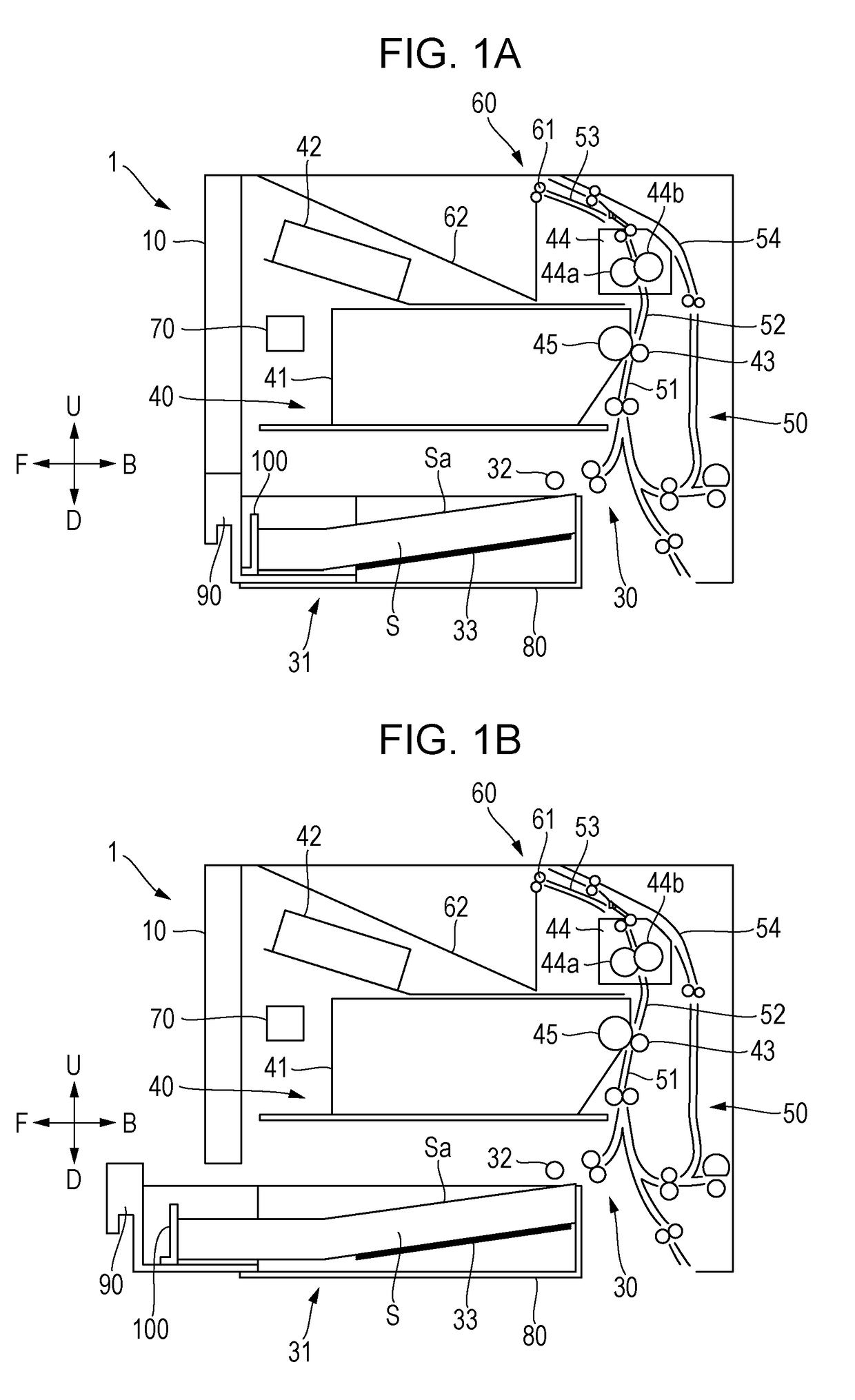
[0042]Embodiments of the present disclosure will be described hereinbelow with reference to the drawings. FIGS. 1A and 1B are diagrams illustrating, in outline, the configuration of a laser printer, which is an example of an image forming apparatus equipped with a sheet feeding apparatus according to the present disclosure. In the following description, the near side when the viewer faces the laser printer is the front, further from the viewer is the back, the left is a leftward direction, the right is a rightward direction, the above is an upward direction, and the down is a downward direction. In FIGS. 1A and 1B and the other diagrams, arrow F indicates the front, arrow B indicates the back, arrow L indicates the leftward direction, arrow R indicate the rightward direction, arrow U indicate the upward direction, and arrow D indicates the downward direction.
[0043]As shown in FIGS. 1A and 1B, the laser printer 1 includes a printer main body 10, which is an image forming apparatus ma...
second embodiment
[0078]the present disclosure will be described. FIG. 6 is a diagram illustrating the configuration of a trailing-end restricting unit provided at a sheet cassette of a sheet feeding apparatus according to this embodiment. In FIG. 6, the same reference signs as those in FIGS. 3A and 3B denote the same or corresponding parts.
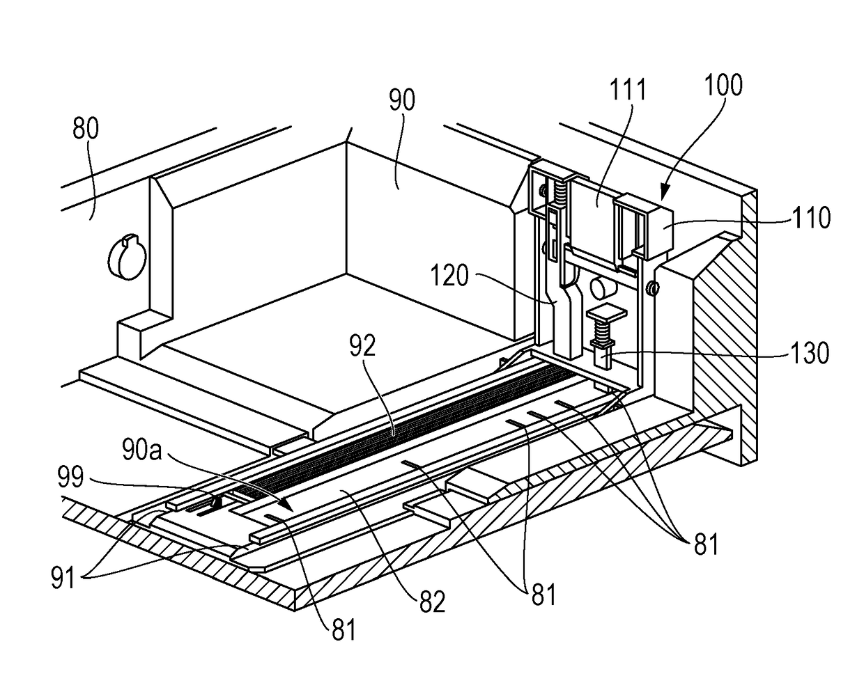
[0079]As shown in FIG. 6, the trailing-end restricting unit 100 includes an engaging member 140 (hereinafter referred to as “third engaging member”) having claws 140d at the bottom to engage with the main cassette 80, in addition to the trailing-end restricting case 110, the first engaging member 130, and the second engaging member 120. The trailing-end restricting unit 100 further includes a third elastic member 141 that urges the third engaging member 140 downwards. The third engaging member 140 is disposed beside the first engaging member 130. The trailing-end restricting case 110 vertically movably supports the second engaging member 120, the first engaging me...
third embodiment
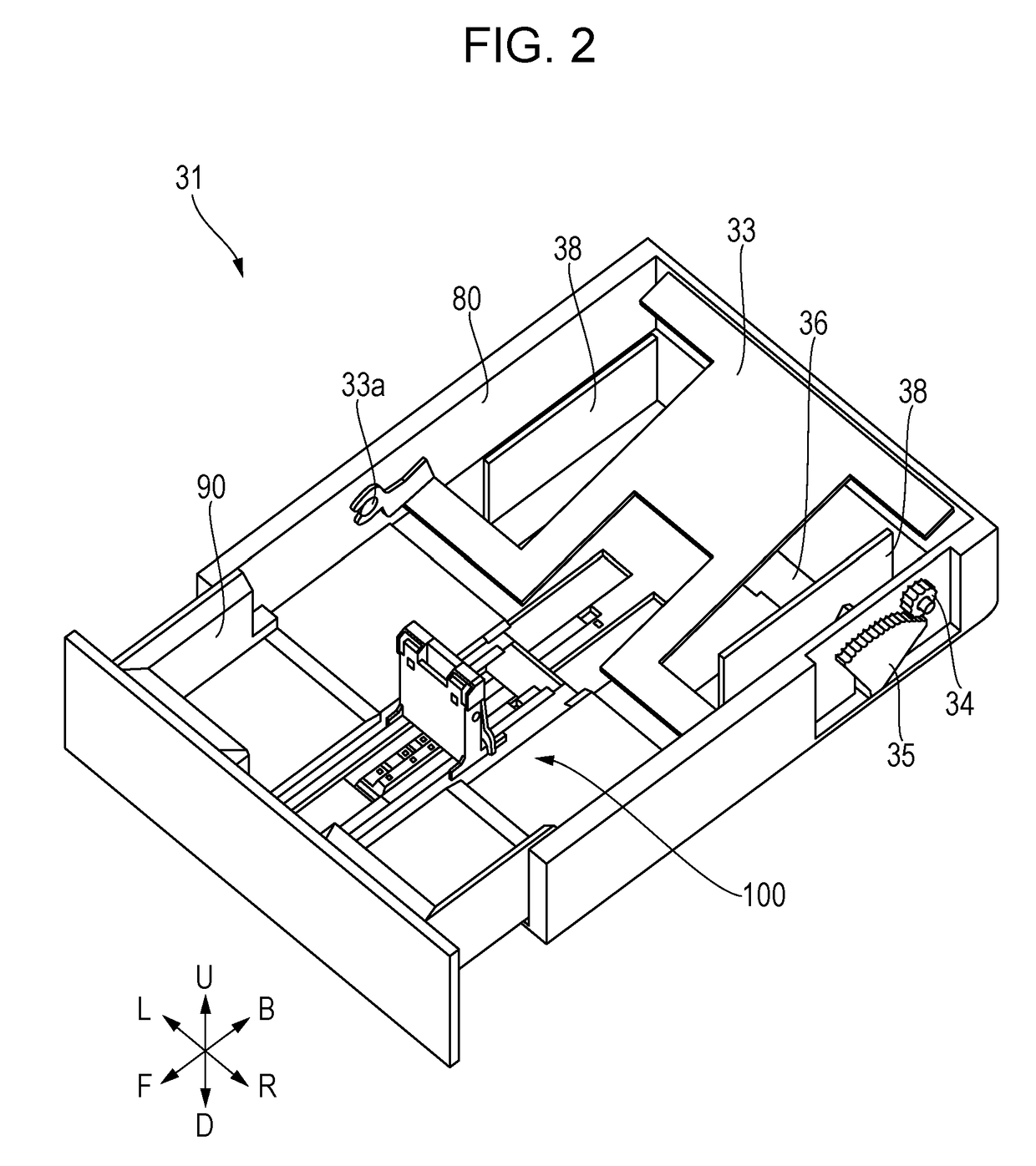
[0100]Next, the present disclosure will be described. FIG. 12 is a diagram illustrating the configuration of a sheet cassette of a sheet feeding apparatus according to this embodiment. In FIG. 12, the same reference signs as those of FIGS. 5A and 5B denote the same or corresponding parts. For the sheet cassette 31 of this embodiment, the largest-size sheet of the small standard-size sheets is an A4-size sheet of portrait orientation, and the largest-size sheet of the large standard-size sheets is a ledger-size sheet of portrait orientation. Between the A4-size of portrait orientation and the ledger-size of portrait orientation, legal-size of portrait orientation and A3-size of portrait orientation are standard sizes.
[0101]As shown in FIG. 12, the trailing-end restricting unit 100 includes an engaging member 150 (hereinafter referred to as “fourth engaging member”) having a tapered engaging portion (not shown) at the bottom to engage with the extension cassette 90, in addition to the...
PUM
 Abstract
Description
Claims
Application Information
 - R&D
- Intellectual Property
- Life Sciences
- Materials
- Tech Scout
- Unparalleled Data Quality
- Higher Quality Content
- 60% Fewer Hallucinations
Browse by: Latest US Patents, China's latest patents, Technical Efficacy Thesaurus, Application Domain, Technology Topic, Popular Technical Reports.
© 2025 PatSnap. All rights reserved.Legal|Privacy policy|Modern Slavery Act Transparency Statement|Sitemap|About US| Contact US: help@patsnap.com