
Bending device
The technology of a press-bending device and a hydraulic cylinder is applied in the field of press-bending devices, which can solve the problems of high risk, poor bending effect, complicated operation, etc., and achieve the effects of high work efficiency, reasonable structure, and safe installation and use.
Patent Information
- Authority / Receiving Office
- CN · China
- Current Assignee / Owner
- Publication Date
- 2016-06-22
- Estimated Expiration
- Not applicable · inactive patent
Smart Images
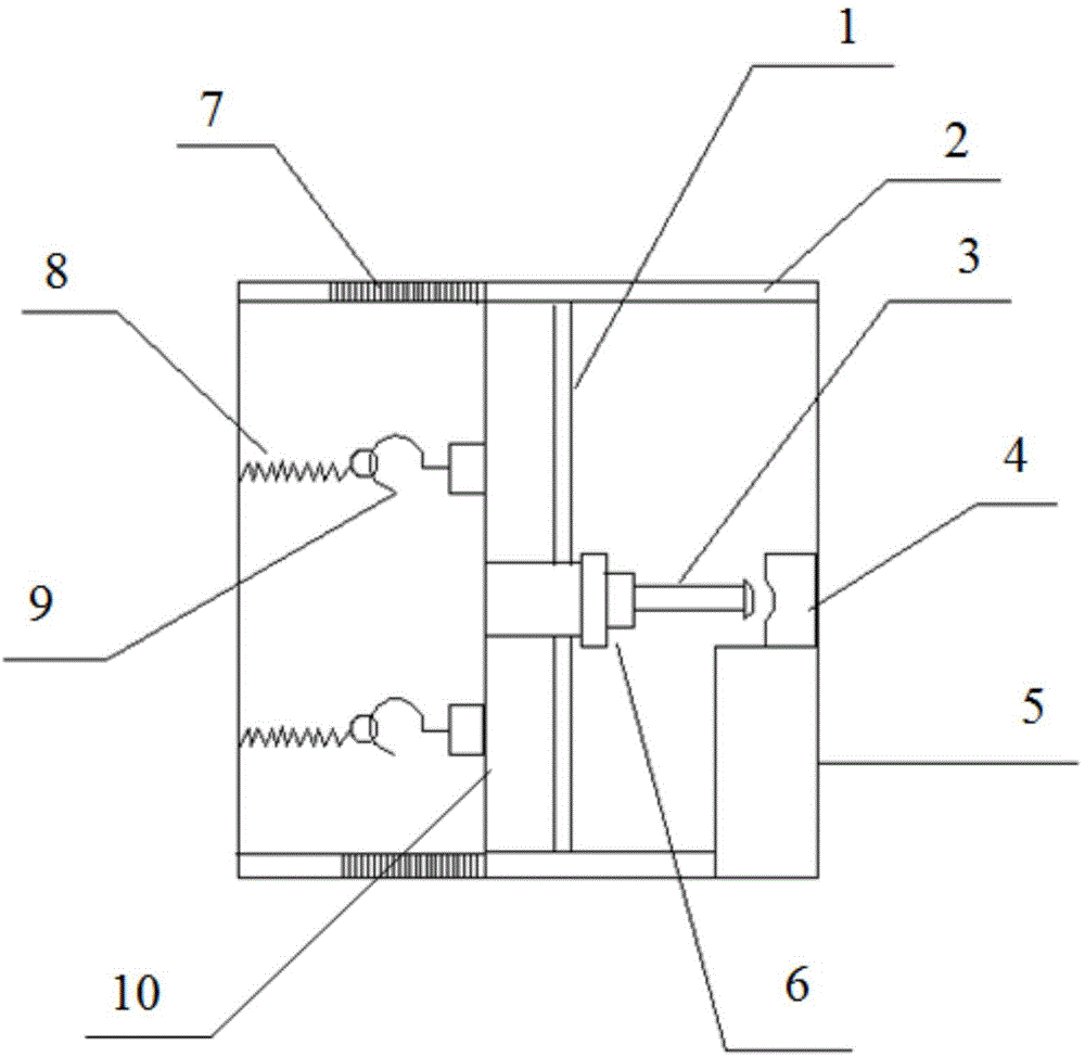
Figure 1
Abstract
Description
technical field
[0001] The invention belongs to the technical field, and in particular relates to a bending device. Background technique
[0002] In industrial production, it is often necessary to bend metal workpieces such as pipe fittings and plates. At present, the commonly used bending device is relatively cumbersome to operate, has high risk, and the bending effect is not good. For this reason, it is very necessary that we provide a kind of novel bending device. Contents of the invention
[0003] The problem to be solved by the present invention is to provide a bending device with reasonable structural design and high working efficiency.
[0004] In order to solve the above technical problems, the technical solution adopted by the present invention is: a bending device, including a stamping mechanism, a support mechanism and a position adjustment mechanism, and the stamping mechanism includes a hydraulic cylinder, an upper mold, a lower mold, a bearing plate and a m...
Examples
Example Embodiment
[0012] The specific embodiments of the present invention will be described in detail below with reference to the accompanying drawings.
[0013] A press bending device includes a press mechanism, a support mechanism, and a position adjustment mechanism. The press mechanism includes a hydraulic cylinder 6, an upper die 3, a lower die 4, a bearing plate 10 and a material table 5. The press mechanism is placed in the press bending Inside the device, the supporting mechanism includes a supporting rod 1, a guide groove 2 and a stopper 7, the guide groove 2 is placed at the top and bottom of the bending device, the stopper 7 is placed on the left side of the guide groove 2, and the load bearing The two ends of the plate 10 are placed in the baffles 7, the hydraulic cylinder 6 is fixedly connected to the bearing plate 10, the upper mold 3 is fixedly connected to the bottom of the hydraulic cylinder 6, and the lower mold 4 is placed on the right side of the upper mold 3. The material tab...