
Non-navigable span pier collision avoidance monitoring system and real-time diagnosis method
A monitoring system and real-time diagnosis technology, applied in the testing of machine/structural components, measuring devices, impact testing, etc., can solve the problem of increased construction investment, uneconomical and uneconomical benefits, and the inability of non-navigation hole bridges to achieve collision avoidance with main navigation holes abilities, etc.
Patent Information
- Authority / Receiving Office
- CN · China
- Current Assignee / Owner
- Publication Date
- 2016-12-21
Smart Images
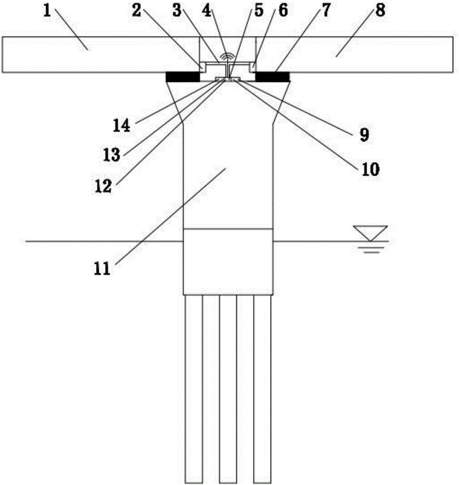
Figure 1 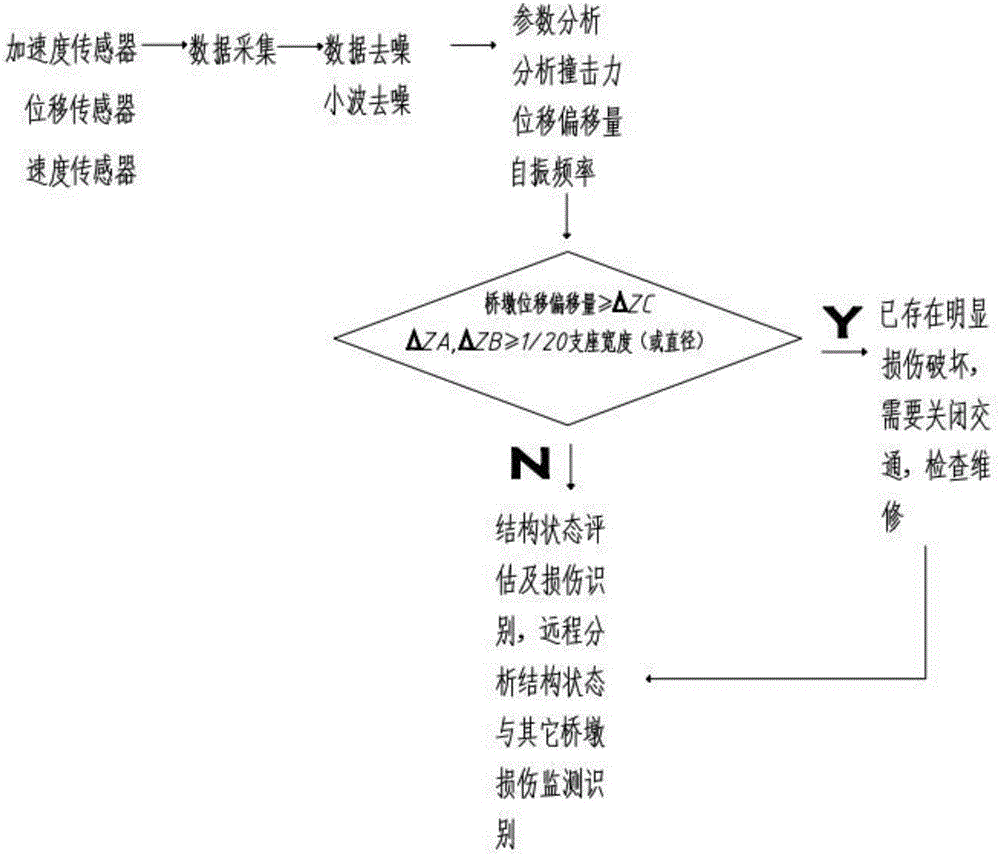
Figure 2 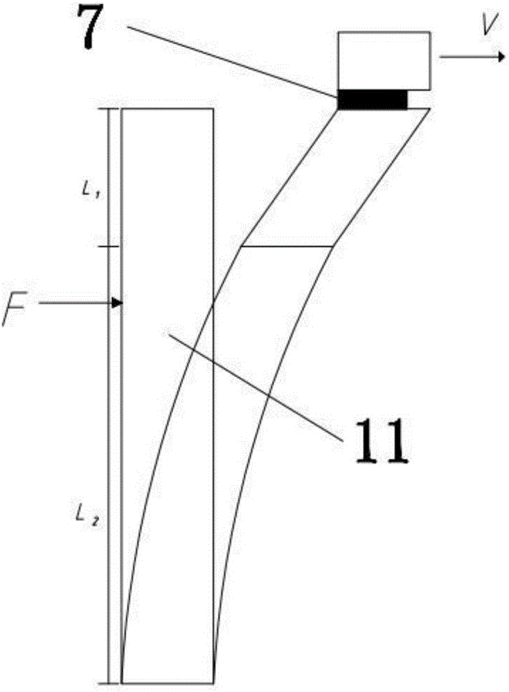
Figure 3
Abstract
Description
technical field
[0001] The invention belongs to the technical field of bridge pier monitoring, and in particular relates to a monitoring system and a real-time diagnosis method for bridge pier anti-collision. Background technique
[0002] The international systematic research on the problem of ship collision with bridges began in the early 1980s, and then domestic and foreign scholars carried out a lot of research in the field of ship collision risk analysis and ship bridge impact force, and put forward the bridge anti-collision risk assessment for design method and impact force value method, and began to formulate relevant design specifications. In 1991, the American Association of Highway Engineers (AASHTO) published the first design guidelines for bridges subjected to ship impact. Since the 1990s, with the construction of large-scale cross-sea bridges, scholars at home and abroad have carried out a large number of bridge anti-collision technology researches based on the ...
Examples
Embodiment Construction
[0045] In order to enable those skilled in the art to better understand the solution of the present invention, the present invention will be further described in detail below in conjunction with the accompanying drawings and specific embodiments.
[0046] see figure 1 , a kind of anti-collision monitoring system of non-navigable piers of the present invention is installed on bridge A 1, bridge B 8 and bridge piers 11, and rubber bearings 7 are all provided between bridge A 1, bridge B 8 and bridge piers 11, Including sensor A2, sensor B6 and sensor 5 respectively arranged on bridge A1, bridge B 8 and pier 11, sensor A2, sensor B6 and sensor 5 are connected and fixed by T-shaped steel pipe 3 to form a T-shaped structure, sensor A2 and sensor B6 are installed The specific location is on the edge of the bridge deck of bridge A1 and bridge B8, the upper part of rubber bearing 7, close to bridge A1 and bridge B8, and the sensor 5 is installed on the top of bridge pier 11, which is ...