
Supporting anti-toppling device for film and television projection screen
An anti-dumping and screen technology, applied to projection devices, supporting machines, machine tables/supports, etc., can solve problems such as unstable supports, reduce equipment costs, meet user needs, and ensure stability
Patent Information
- Authority / Receiving Office
- CN · China
- Current Assignee / Owner
- Publication Date
- 2022-02-25
Smart Images
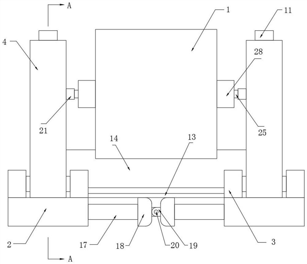
Figure 1 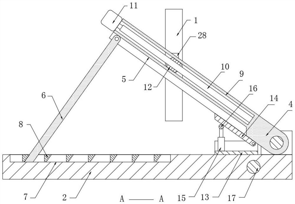
Figure 2 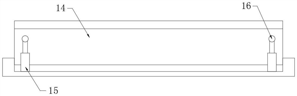
Figure 3
Abstract
Description
technical field
[0001] The invention relates to the technical field of screen support, in particular to a screen support anti-dumping device for film and television projecting. Background technique
[0002] Screen, which refers to the white screen that displays the projection when playing a movie, is widely used in theme parks, museums, studios, TV and film studios, scenic spots, churches, medical and educational facilities, and conference rooms;
[0003] When the screen is in use, it usually needs to be supported to meet the projection requirements. At present, the support for the screen is basically in the form of binding the support rod around the support column with a drawstring, which is completed by bolt fixing, rope binding, etc. There is also instability in itself, so that even if the screen and the supporting parts are combined stably, the overall stability is still insufficient, and most of the supporting parts are directly placed vertically, if the angle adjustmen...
Examples
Embodiment
[0028] refer to Figure 1-6 , a support anti-dumping device for film and television projection, comprising a screen body 1 and two bases 2, the upper ends of the two bases 2 are provided with a support mechanism, the support mechanism includes a mounting frame 3 fixed on the upper end of the base 2, and the mounting frame 3 The side wall is rotatably connected with a support frame 4, the bottom of the support frame 4 is provided with a storage slot 5, the inner wall of the storage slot 5 is rotatably connected with a support plate 6, and the upper end of the base 2 is provided with a draw-in slot 7, and the inner wall of the draw-in slot 7 is fixed with multiple There are four blocks 8, one of which blocks against the support plate 6, the side wall of the support frame 4 is provided with an adjustment groove 9, the inner wall of the adjustment groove 9 is rotatably connected with an adjustment screw 10, and the end of the support frame 4 is fixed with an adjustment Motor 11, t...