
Safety locking device for guide shoes of super-large and super-heavy vehicle elevator
Patent Information
- Application Number
- CN202522104554.2
- Authority / Receiving Office
- CN · China
- Patent Type
- Utility models(China)
- Current Assignee / Owner
- Filing Date
- 2025-09-29
- Publication Date
- 2026-10-09
- Estimated Expiration
- 2035-09-29
AI Technical Summary
然而,当超大超重车辆等重物进入电梯轿厢的过程中,由于车辆自身重量极大且进入时易产生横向冲击或偏载力,轿厢易因受力不均衡而发生横向晃动、偏移甚至与导轨产生相对位移
本实用新型通过设置活动压板与驱动构件配合,在重物进入电梯前,活动压板能夹压导轨实现轿厢锁死,有效避免重物进入时因冲击、偏载导致的轿厢晃动或偏移,从根本上降低了重物进出阶段的安全隐患。
Smart Images
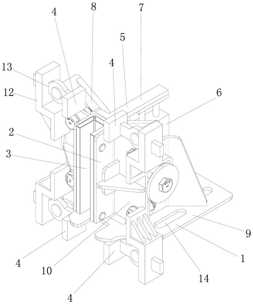
Figure CN224831740U_ABST
Abstract
Description
Technical Field
[0001] This utility model specifically relates to a guide shoe safety locking device for elevators of ultra-large and ultra-heavy vehicles. Background Technology
[0002] In logistics, transportation, and heavy industrial production, oversized and overweight vehicles (such as heavy trucks and engineering vehicles) often require specialized elevators for vertical transportation. These elevators, as special load-bearing equipment, can carry tens or even hundreds of tons at a time, far exceeding the load-bearing standards of ordinary passenger or freight elevators. In existing technologies, elevator cars carrying oversized and overweight vehicles are guided vertically using guide shoes that work in conjunction with guide rails. Guide shoes typically serve only a guiding and cushioning function, and their structure mainly includes a base, a frame, and a shoe liner on the frame. The shoe liner slides against the guide rail to reduce running friction. However, when oversized and overweight vehicles or other heavy objects enter the elevator car, the vehicle's immense weight and the resulting lateral impact or uneven load can cause the car to sway laterally, deviate, or even shift relative to the guide rails due to uneven force distribution. In this situation, traditional guide shoes can only provide guidance and cannot temporarily lock and secure the car, resulting in extremely poor stability during the loading and unloading of heavy objects. This can lead to difficulties in vehicle loading and unloading, excessive wear on the shoe liner, or even car tilting, guide rail deformation, and ultimately, elevator malfunctions or safety accidents, seriously threatening equipment and personnel safety. Utility Model Content
[0003] In view of the defects of the existing technology, the technical problem to be solved by this utility model is to provide a guide shoe safety locking device for an elevator for ultra-large and ultra-heavy vehicles. A guide shoe safety locking device for an ultra-large and ultra-heavy vehicle elevator includes a base and a bushing. A shoe liner is provided on the bushing. Two movable pressure plates are symmetrically and movably arranged on the base and above the bushing. The two movable pressure plates can move closer or further apart. The base is provided with a driving component that can drive the two movable pressure plates to move.
[0004] In one embodiment, the driving component includes a cylinder, a movable rod, and two connecting rods. The cylinder is mounted on a base, the movable rod is movably mounted on the base and connected to the driving end of the cylinder, and the connecting rods are hinged one-to-one between the movable rod and the movable pressure plate.
[0005] In one embodiment, the cylinder is a double-headed cylinder, there are two movable rods, and the two movable rods are respectively connected to the two drive ends of the double-headed cylinder. There are four movable pressure plates, and the four movable pressure plates are respectively located on the outer side of the four corners of the bushing. There are four connecting rods, and the four connecting rods are respectively hinged between the movable pressure plates and the movable rods.
[0006] In one embodiment, friction pads are provided on the opposite inner side of the movable pressure plate.
[0007] In one embodiment, the base includes an integrally formed base plate and a side plate, the bushing is disposed on the front side of the side plate, a first guide hole with openings at the top and bottom is provided on the rear side of the side plate, the movable rod is movably disposed in the first guide hole through a linear bearing, and the cylinder is disposed on the base plate.
[0008] In one embodiment, the side plate is provided with bending members at the four corners, and second guide holes are provided through the bending members on opposite sides. The movable pressure plates are movably inserted into the second guide holes one by one.
[0009] In one embodiment, the base has a plurality of mounting holes spaced through it.
[0010] In one embodiment, a plurality of reinforcing ribs are connected between the base plate and the side plate.
[0011] In summary, the advantages of this utility model over the prior art are: This utility model, by setting a movable pressure plate in cooperation with the driving component, can clamp the guide rail and lock the car before the heavy object enters the elevator, effectively avoiding the car shaking or deviation caused by impact or off-center loading when the heavy object enters, and fundamentally reducing the safety hazards during the entry and exit of heavy objects. Attached image description; Figure 1 This is one of the perspective views of a guide shoe safety locking device for an ultra-large and ultra-heavy vehicle elevator according to one embodiment of the present invention; Figure 2 This is a second perspective view of a guide shoe safety locking device for an ultra-large and ultra-heavy vehicle elevator according to one embodiment of the present invention. Detailed Implementation
[0013] The present invention will be further described below with reference to the accompanying drawings and specific embodiments: like Figures 1 to 2 The present invention preferably provides a guide shoe safety locking device for an ultra-large and ultra-heavy vehicle elevator, including a base 1 and a bushing 2. A shoe liner 3 is provided on the bushing 2. Two movable pressure plates 4 are symmetrically and movably arranged on the base 1 and above the bushing 2. The two movable pressure plates 4 can be moved closer or further apart. A driving member 5 is provided on the base 1 to drive the two movable pressure plates 4 to move.
[0014] Specifically, the movable pressure plate is located on the clamping surface near the guide rail. This clamping surface is adapted to the shape of the outer wall of the guide rail. Before a heavy object enters the elevator, the drive component drives the two movable pressure plates to move closer together until the clamping surfaces of the movable pressure plates are tightly pressed against the two side walls of the guide rail, thus locking and fixing them to the guide rail, thereby locking the car in the current position. When the heavy object enters the elevator car, it effectively avoids lateral impact or off-center load caused by uneven gravity. After the heavy object has completely entered the elevator car and stopped, the drive component drives the two movable pressure plates to move away from each other, releasing the clamping pressure on the guide rail, and the car returns to normal operation.
[0015] Furthermore, the driving component 5 includes a cylinder 6, a movable rod 7, and two connecting rods 8. The cylinder 6 is mounted on the base 1, and the movable rod 7 is movably mounted on the base 1 and connected to the driving end of the cylinder 6. The connecting rods 8 are hinged one-to-one between the movable rod 7 and the movable pressure plate 4. Specifically, both the connecting rod and the movable rod are made of high-strength alloy steel. When the piston rod of the cylinder extends, it drives the movable rod to move upward. The movable rod, through the two connecting rods, pushes the two movable pressure plates away from each other horizontally, releasing the clamping pressure on the guide rail. When the piston rod of the cylinder retracts, it drives the movable rod to move downward. The movable rod, through the two connecting rods, pulls the two movable pressure plates closer together horizontally, locking the guide rail.
[0016] Furthermore, the cylinder 6 is a double-headed cylinder, there are two movable rods 7, and the two movable rods 7 are respectively connected to the two driving ends of the double-headed cylinder. There are four movable pressure plates 4, and the four movable pressure plates 4 are respectively located on the outer sides of the four corners of the bushing 2. There are four connecting rods 8, and the four connecting rods 8 are respectively hinged between the movable pressure plates 4 and the movable rods 7.
[0017] Specifically, when a heavy object is about to enter the elevator, the two piston rods of the double-headed cylinder retract synchronously, driving the two movable rods to move downwards. The two movable rods, through four connecting rods, pull the four movable pressure plates horizontally towards the four corners of the support frame until the four movable pressure plates clamp onto the outer walls of the four corners of the guide rails (both sides), achieving multi-point locking of the guide rails, making them more evenly stressed and stable. When the heavy object has completely entered the elevator car and stopped, the two piston rods of the double-headed cylinder extend synchronously, driving the two movable rods to move upwards, pushing the four movable pressure plates away from the guide rails through the connecting rods, releasing the locking state, and allowing the car to resume normal operation.
[0018] Furthermore, friction pads are provided on the inner sides of the movable pressure plate 4. These friction pads effectively enhance the frictional force when clamping the guide rail.
[0019] Furthermore, the base 1 includes an integrally formed base plate 9 and side plate 10. The bushing 2 is disposed on the front side of the side plate 10, and a first guide hole 11 with upper and lower openings is provided on the rear side of the side plate 10. The movable rod 7 is movably disposed in the first guide hole 11 through a linear bearing, and the cylinder 6 is disposed on the base plate 9. Thus, the vertical linear guiding displacement of the movable rod is realized through the first guide hole.
[0020] Furthermore, each of the four corners of the side plate 10 is provided with a bending member 12, and a second guide hole 13 is provided on the opposite side of each bending member 12. The movable pressure plate 4 is movably inserted into the second guide hole 13 in a corresponding manner. Thus, the horizontal lateral displacement of the movable pressure plate is realized through the second guide hole.
[0021] Furthermore, the base is provided with a plurality of mounting holes 14 spaced apart. Bolts are then used in the mounting holes to securely connect it to the elevator car.
[0022] Furthermore, several reinforcing ribs are connected between the base plate 9 and the side plate 10 to effectively increase the structural strength.
[0023] The foregoing has shown and described the basic principles and main features of this utility model, as well as its advantages. Those skilled in the art should understand that this utility model is not limited to the above embodiments. The embodiments and descriptions in the specification are merely illustrative of the principles of this utility model. Various changes and modifications can be made to this utility model without departing from its spirit and scope, and all such changes and modifications fall within the scope of the claimed utility model. The scope of protection of this utility model is defined by the appended claims and their equivalents.
Claims
1. A guide shoe safety locking device for an ultra-large and ultra-heavy vehicle elevator, comprising a base (1) and a bushing (2), wherein a shoe liner (3) is provided on the bushing (2), characterized in that: Two movable pressure plates (4) are symmetrically and movably arranged on the base (1) and above the bushing (2). The two movable pressure plates (4) can be positioned relatively close to or far apart. The base (1) is provided with a driving component (5) that can drive the two movable pressure plates (4) to move.
2. The guide shoe safety locking device for an ultra-large and ultra-heavy vehicle elevator according to claim 1, characterized in that: The driving component (5) includes a cylinder (6), a movable rod (7) and two connecting rods (8). The cylinder (6) is mounted on the base (1). The movable rod (7) is mounted on the base (1) and connected to the driving end of the cylinder (6). The connecting rods (8) are hinged one-to-one between the movable rod (7) and the movable pressure plate (4).
3. The guide shoe safety locking device for an ultra-large and ultra-heavy vehicle elevator according to claim 2, characterized in that: The cylinder (6) is a double-headed cylinder. There are two movable rods (7), and the two movable rods (7) are connected to the two driving ends of the double-headed cylinder respectively. There are four movable pressure plates (4), and the four movable pressure plates (4) are located on the outer side of the four corners of the bushing (2). There are four connecting rods (8), and the four connecting rods (8) are hinged between the movable pressure plates (4) and the movable rods (7) respectively.
4. The guide shoe safety locking device for an ultra-large and ultra-heavy vehicle elevator according to claim 1, characterized in that: The movable pressure plate (4) is provided with friction pads on its inner side.
5. The guide shoe safety locking device for an ultra-large and ultra-heavy vehicle elevator according to claim 2, characterized in that: The base (1) includes an integrally formed base plate (9) and side plate (10). The bushing (2) is located on the front side of the side plate (10). A first guide hole (11) with an upper and lower opening is provided on the rear side of the side plate (10). The movable rod (7) is movably set in the first guide hole (11) through a linear bearing. The cylinder (6) is located on the base plate (9).
6. The guide shoe safety locking device for an ultra-large and ultra-heavy vehicle elevator according to claim 1, characterized in that: The side plate (10) is provided with bending parts (12) at the four corners respectively, and second guide holes (13) are provided on the opposite side of the bending parts (12). The movable pressure plate (4) is movably inserted into the second guide hole (13) in a corresponding manner.
7. The guide shoe safety locking device for an ultra-large and ultra-heavy vehicle elevator according to claim 1, characterized in that: The base has several mounting holes (14) spaced through it.
8. The guide shoe safety locking device for an ultra-large and ultra-heavy vehicle elevator according to claim 1, characterized in that: Several reinforcing ribs connect the bottom plate (9) and the side plate (10).