
Engineering Drawing vs 3D Model: Which Defines Final Part Specs?
AUG 7, 20269 MIN READ
Generate Your Research Report Instantly with AI Agent
Patsnap Eureka helps you evaluate technical feasibility & market potential.
Engineering Documentation Evolution and Definition Authority Goals
The engineering documentation landscape has undergone profound transformation over the past several decades, fundamentally reshaping how product specifications are defined, communicated, and enforced across manufacturing enterprises. Historically, 2D engineering drawings served as the unequivocal master definition for part specifications, establishing dimensional tolerances, geometric controls, material requirements, and surface finishes through standardized annotation practices. This paradigm persisted for over a century, creating deeply embedded workflows, legal frameworks, and quality assurance protocols centered on paper-based or PDF documentation.
The advent of computer-aided design systems in the 1980s introduced 3D solid modeling capabilities, initially serving as design tools that generated traditional 2D drawings for manufacturing consumption. However, as CAD technology matured through the 1990s and 2000s, 3D models evolved from mere visualization aids into information-rich digital assets capable of embedding comprehensive product and manufacturing information directly within the geometric representation. This technological evolution precipitated a fundamental question regarding definition authority: should the 3D model or the 2D drawing constitute the authoritative source of product specifications?
The transition toward Model-Based Definition and Model-Based Enterprise methodologies represents an industry-wide effort to establish 3D models as the single source of truth, eliminating redundancy and potential conflicts between drawing and model representations. This shift aims to achieve multiple strategic objectives including reduced documentation cycle times, improved data consistency across engineering and manufacturing systems, enhanced automation of downstream processes, and elimination of interpretation errors inherent in translating 3D geometry into 2D projections.
Contemporary organizations face critical decisions regarding definition authority governance, balancing the efficiency gains of model-centric workflows against established regulatory requirements, supplier capabilities, and legacy system constraints. The goal of this technical investigation is to comprehensively analyze the comparative advantages, implementation challenges, and strategic implications of designating either engineering drawings or 3D models as the authoritative specification source, providing actionable guidance for enterprises navigating this documentation paradigm transition while maintaining product quality, regulatory compliance, and supply chain interoperability.
Market Demand for Digital Manufacturing Documentation Standards
The manufacturing industry is undergoing a fundamental transformation driven by digital technologies, creating unprecedented demand for standardized digital documentation frameworks. Traditional engineering drawings, once the undisputed source of truth for part specifications, are increasingly challenged by 3D model-based definitions (MBD) as manufacturers seek to eliminate ambiguity, reduce errors, and accelerate production cycles. This shift reflects broader industry recognition that inconsistent documentation practices lead to costly misinterpretations, quality issues, and supply chain inefficiencies.
Aerospace and automotive sectors have emerged as primary drivers of digital documentation standardization, where complex assemblies and stringent regulatory requirements necessitate unambiguous specification methods. These industries face mounting pressure to reduce time-to-market while maintaining zero-defect manufacturing standards. The proliferation of global supply chains further amplifies the need for universally interpretable documentation that transcends language barriers and regional drafting conventions.
Small and medium enterprises increasingly demand accessible digital standards as they integrate into larger manufacturing ecosystems. These organizations require clear guidance on whether to invest in 3D model infrastructure or maintain traditional drawing-based workflows. The market shows strong appetite for hybrid approaches that preserve existing investments while enabling gradual digital transformation, particularly in sectors with legacy systems and established supplier networks.
Regulatory bodies and industry consortia are responding to this demand through initiatives like ISO 16792 and ASME Y14.41, which establish frameworks for model-based definition. However, significant gaps remain in addressing practical implementation challenges, legal enforceability of digital specifications, and interoperability across diverse CAD platforms. Manufacturers express particular concern about intellectual property protection and data security when transitioning to model-centric workflows.
The rise of additive manufacturing and advanced machining technologies intensifies demand for precise digital specifications that capture geometric dimensioning and tolerancing information in machine-readable formats. These emerging production methods cannot efficiently utilize traditional 2D drawings, creating market pressure for standardized 3D annotation practices. Contract manufacturers and inspection service providers increasingly require clarification on which documentation format holds contractual authority when discrepancies arise between drawings and models.
Current Conflicts Between 2D Drawings and 3D Model Specifications
The fundamental conflict between 2D engineering drawings and 3D CAD models emerges from their parallel existence as specification sources in modern manufacturing environments. Traditionally, 2D drawings served as the sole legal document defining part requirements, containing dimensions, tolerances, surface finishes, and material specifications. However, the widespread adoption of 3D modeling has introduced a dual-documentation scenario where both representations coexist, often containing overlapping yet potentially contradictory information.
A primary source of conflict arises when dimensional data differs between the 2D drawing and the 3D model. Manufacturing teams frequently encounter situations where a dimension explicitly stated on the drawing does not match the corresponding measurement extracted from the 3D model. This discrepancy typically occurs due to design changes being implemented in one format but not properly synchronized with the other, creating ambiguity about which specification represents the designer's true intent.
Geometric Dimensioning and Tolerancing (GD&T) annotations present another significant conflict area. While 2D drawings display GD&T callouts with specific datum references and tolerance zones, the 3D model may contain Model-Based Definition (MBD) annotations that interpret these requirements differently. The translation of complex tolerance schemes between 2D and 3D formats often introduces inconsistencies, particularly for features involving multiple datum references or composite tolerances.
Surface finish specifications and material callouts frequently appear only on 2D drawings, while the 3D model remains silent on these critical manufacturing parameters. Conversely, 3D models may contain detailed geometric information about complex surfaces that cannot be adequately represented in 2D views, forcing manufacturers to decide which source takes precedence for different aspects of part definition.
The legal and contractual implications of these conflicts create substantial risk exposure. When disputes arise regarding part conformance, the question of which document holds authority becomes critical. Many organizations still designate the 2D drawing as the controlling document through notes stating "in case of conflict, the drawing governs," yet this approach undermines the efficiency gains promised by model-based workflows.
Version control misalignment exacerbates these conflicts when drawings and models are revised independently or at different frequencies. A model may be updated to revision C while its associated drawing remains at revision B, leaving manufacturers uncertain about which specifications apply to current production requirements.
Existing Approaches for Drawing-Model Specification Hierarchy
01 Automated generation of engineering drawings from 3D models
Systems and methods for automatically generating engineering drawings, including orthographic views, section views, and detail views, directly from 3D CAD models. The automation process includes extracting geometric data, determining optimal view orientations, and generating dimensioned drawings with annotations according to standard drafting conventions. This approach reduces manual drafting time and ensures consistency between the 3D model and 2D documentation.- Automated generation of engineering drawings from 3D models: Systems and methods for automatically generating engineering drawings, including orthographic views, cross-sections, and dimensioned drawings, directly from 3D CAD models. The technology enables automatic extraction of geometric features, dimensions, and annotations from the 3D model data to create standardized 2D engineering drawings without manual drafting. This includes automatic view generation, hidden line removal, and dimension placement according to drafting standards.
- 3D model-based part specification and tolerance management: Methods for defining and managing part specifications directly within 3D models, including geometric dimensioning and tolerancing (GD&T), surface finish requirements, and material specifications. The technology allows engineers to embed complete manufacturing specifications into the 3D model itself, creating a model-based definition that serves as the authoritative source for part requirements. This approach eliminates the need for separate 2D drawings while maintaining all necessary manufacturing information.
- Conversion and synchronization between 2D drawings and 3D models: Systems for bidirectional conversion and synchronization between traditional 2D engineering drawings and 3D CAD models. The technology enables updating 3D models based on changes made to 2D drawings and vice versa, maintaining consistency between both representations. This includes feature recognition from 2D drawings to reconstruct 3D geometry, and automatic update propagation when modifications are made to either representation.
- Parametric modeling and specification-driven design: Technologies for creating parametric 3D models where part geometry is driven by design specifications and parameters. The system allows engineers to define relationships between dimensions, features, and specifications such that changes to input parameters automatically update the model geometry. This includes constraint-based modeling, feature-based design, and the ability to create families of parts from a single parametric template with varying specifications.
- Digital twin and model-based manufacturing integration: Systems that integrate 3D model specifications with manufacturing processes and digital twin technologies. The technology enables direct use of 3D model data for manufacturing planning, CNC programming, quality inspection, and production documentation. This includes methods for extracting manufacturing features from 3D models, generating toolpaths, creating inspection programs, and maintaining traceability between design specifications and manufactured parts throughout the product lifecycle.
02 Specification extraction and management from 3D part models
Methods for extracting, organizing, and managing part specifications and metadata from 3D models, including dimensional tolerances, material properties, surface finish requirements, and manufacturing constraints. The systems enable automatic population of bills of materials, specification sheets, and technical documentation based on model attributes and embedded information. Integration with product lifecycle management systems ensures specification consistency across design iterations.Expand Specific Solutions03 Dimensional annotation and tolerance specification in 3D environments
Techniques for applying dimensional annotations, geometric dimensioning and tolerancing symbols, and manufacturing specifications directly within 3D modeling environments. The methods include intelligent placement of dimensions based on feature recognition, automatic tolerance stack-up analysis, and validation of specification completeness. Model-based definition approaches eliminate the need for separate 2D drawings while maintaining all necessary manufacturing information.Expand Specific Solutions04 Interoperability and data exchange between CAD systems
Solutions for ensuring accurate transfer of 3D models, engineering drawings, and part specifications between different CAD platforms and manufacturing systems. The approaches include neutral file format conversion, preservation of parametric features and annotations during translation, and validation of data integrity after exchange. Standards-based protocols enable seamless collaboration across organizations using diverse software tools.Expand Specific Solutions05 Visualization and comparison of part specifications across design versions
Systems for visualizing, comparing, and tracking changes in part specifications and 3D geometry across multiple design revisions. The methods include automated detection of dimensional changes, specification modifications, and geometric differences between model versions. Visual highlighting and reporting tools help engineers quickly identify and review design changes for approval and manufacturing impact assessment.Expand Specific Solutions
Key Players in CAD and Model-Based Definition Solutions
The competitive landscape for engineering drawing versus 3D model specifications reflects a maturing industry transitioning from traditional documentation to digital-first workflows. The market demonstrates significant scale with established global players like Autodesk, Siemens Industry Software, and Dassault Systèmes dominating the PLM and CAD software segments, alongside enterprise solution providers such as Tata Consultancy Services and L&T Technology Services. Technology maturity varies across the ecosystem: while companies like Procore Technologies and Bluebeam have achieved robust cloud-based collaboration platforms, emerging players including Hangzhou Qunhe Information Technology and Beijing Gouli Technology are advancing AI-driven design automation. Chinese construction firms like China Construction Third Engineering Bureau and research institutions including Institute of Computing Technology are actively developing indigenous BIM capabilities. The sector shows convergence between traditional engineering software and intelligent construction technologies, with increasing emphasis on digital twin integration and real-time specification management across the product lifecycle.
Procore Technologies, Inc.
Technical Solution: Procore's construction management platform addresses the engineering drawing versus 3D model specification challenge primarily from a construction execution and coordination perspective rather than detailed part manufacturing. Their system serves as a central repository where both 2D construction drawings and 3D BIM (Building Information Modeling) models coexist, with the platform facilitating version control and distribution to field teams. Procore's approach typically maintains 2D construction drawings as the contractually binding documents while leveraging 3D models for coordination, clash detection, and visualization purposes. The platform's document management system tracks revisions, RFIs (Requests for Information), and submittals tied to both drawing sets and model elements, though it does not inherently resolve which format holds specification authority—this remains a project-specific contractual decision. Their field productivity tools allow workers to access both 2D plans and 3D model viewers on mobile devices for construction guidance.
Strengths: Excellent document management and version control; strong mobile field access; effective coordination between 2D and 3D information. Weaknesses: Does not provide definitive specification authority resolution; focused on construction rather than precision manufacturing; limited parametric or annotation capabilities.
Siemens Industry Software, Inc.
Technical Solution: Siemens provides integrated Product Lifecycle Management (PLM) solutions that establish Model-Based Definition (MBD) as the authoritative source for part specifications. Their NX software enables comprehensive 3D model-based engineering where geometric dimensioning and tolerancing (GD&T), material specifications, surface finish requirements, and manufacturing process information are directly embedded within the 3D CAD model using Product Manufacturing Information (PMI). The system supports ISO 16792 standards for 3D annotation and maintains bi-directional associativity between 3D models and derivative 2D drawings. Their Teamcenter platform manages the digital thread ensuring that the 3D model serves as the single source of truth throughout design, manufacturing, and quality inspection processes, while automatically generating compliant 2D drawings when required for legacy systems or regulatory purposes.
Strengths: Industry-leading MBD implementation with comprehensive PMI capabilities; seamless integration across design-manufacturing-quality workflows; strong standards compliance. Weaknesses: High implementation costs; requires significant organizational change management; steep learning curve for traditional 2D-trained engineers.
Core Standards for Model-Based Enterprise Implementation
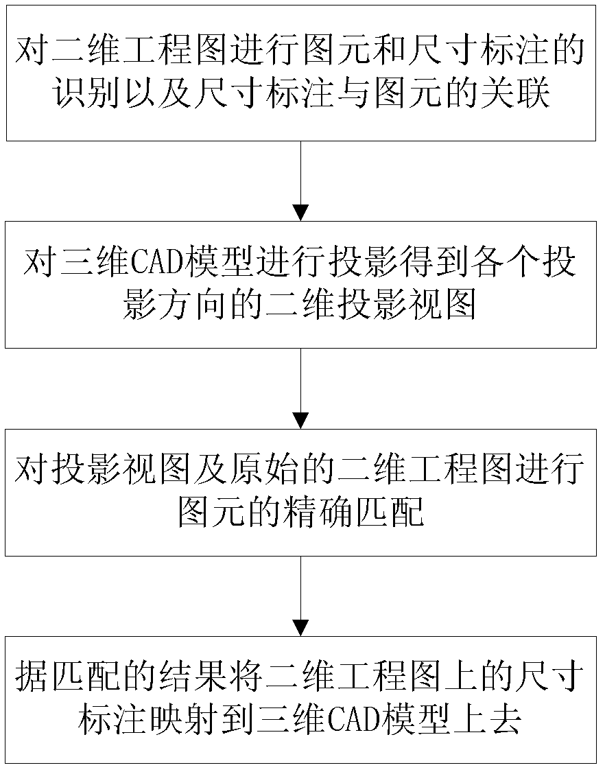
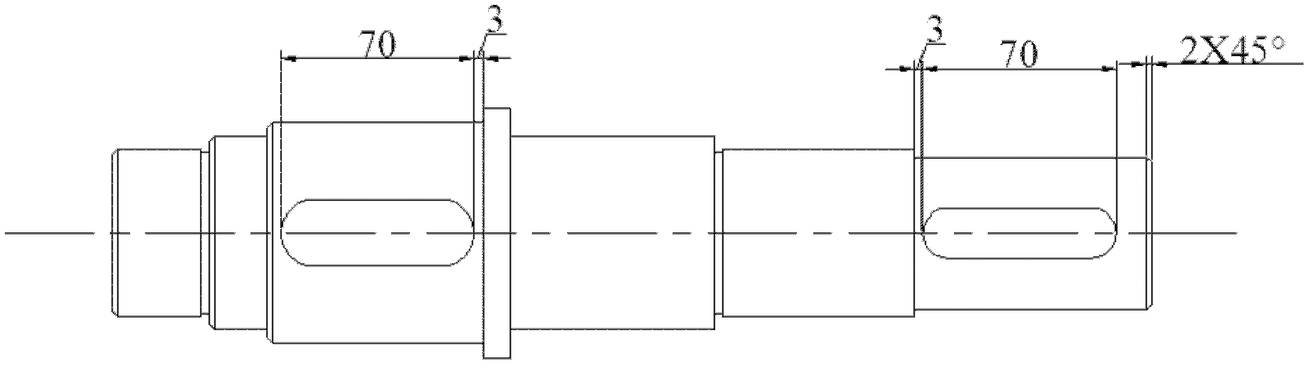
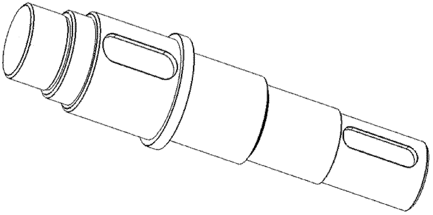
Method for translating dimensions on two-dimensional engineering drawing to three-dimensional CAD (computer aided design) model
PatentInactiveCN102568038B
Innovation
- By identifying the elements and dimension annotations of the two-dimensional engineering drawings, combined with the projection view of the three-dimensional CAD model, the spatial relationship diagram structure is established, and the elements are accurately matched to reduce the number of matches and improve the annotation efficiency.

Model and technical documents
PatentActiveUS11709974B2
Innovation
- The introduction of a 'document space' concept within the digital model, which acts as an intermediary between technical documents and the model, allowing for the creation, manipulation, and display of technical documents in a 3D environment, enabling users to identify and manage missing documents within the modeling system.


Legal and Contractual Implications of Documentation Authority
The determination of whether engineering drawings or 3D models hold ultimate authority in defining final part specifications carries profound legal and contractual ramifications that organizations must carefully navigate. Traditional contract law has historically recognized 2D engineering drawings as the legally binding document of record, establishing precedents that continue to influence modern manufacturing agreements. However, the increasing adoption of model-based definition (MBD) practices has created a transitional landscape where contractual frameworks must explicitly address documentation hierarchy to prevent disputes and liability issues.
In conventional procurement contracts, engineering drawings have served as the primary reference for acceptance criteria, quality assurance, and dispute resolution. When discrepancies arise between documentation types, courts and arbitration bodies typically defer to the document explicitly designated as authoritative within the contract terms. The absence of clear contractual language specifying which documentation governs can lead to costly litigation, particularly when dimensional variations or tolerance interpretations result in rejected parts or system failures. Insurance policies and product liability coverage may also hinge on adherence to specified documentation standards, making this designation critical for risk management.
The shift toward 3D model authority introduces new contractual considerations, including intellectual property rights, data format longevity, and version control protocols. Contracts must address software compatibility requirements, viewing rights, and the legal validity of digital signatures or approval stamps embedded within 3D files. International transactions add complexity, as different jurisdictions maintain varying standards for electronic document authentication and digital record retention. Organizations operating under government contracts face additional scrutiny, as defense and aerospace sectors often mandate specific documentation standards through regulatory frameworks like AS9100 or military specifications.
Liability allocation becomes particularly nuanced when multiple documentation types coexist without clear precedence. Manufacturers may face claims if they follow one document type while customers expected adherence to another. Progressive contracts now incorporate explicit "order of precedence" clauses that rank documentation types, typically stating whether the 3D model, drawing, or written specifications take priority during conflicts. Some organizations adopt hybrid approaches, designating the 3D model as the master definition while requiring 2D drawings for specific inspection or legal purposes, with contractual language carefully delineating each document's scope of authority.
Quality Assurance Workflows for Hybrid Documentation Systems
Establishing robust quality assurance workflows for hybrid documentation systems requires a systematic approach that addresses the inherent complexities of managing both engineering drawings and 3D models as authoritative sources. The primary challenge lies in ensuring consistency, traceability, and accuracy across multiple documentation formats while maintaining compliance with industry standards and regulatory requirements.
The foundation of an effective QA workflow begins with clear documentation hierarchy protocols. Organizations must implement version control systems that synchronize changes between 2D drawings and 3D models, ensuring that modifications in one format trigger appropriate reviews and updates in the other. This synchronization mechanism should include automated flagging systems that alert quality teams when discrepancies arise between the two documentation types, preventing conflicting specifications from reaching production.
Cross-validation procedures form the core of hybrid system quality assurance. These procedures typically involve multi-stage verification processes where dimensional specifications, geometric tolerances, and material callouts are systematically compared between drawings and models. Advanced organizations deploy automated comparison tools that utilize model-based definition (MBD) capabilities to extract data from 3D models and cross-reference it against 2D drawing annotations, significantly reducing human error and inspection time.
Change management protocols must be particularly rigorous in hybrid environments. Every engineering change order (ECO) should mandate parallel updates to both documentation formats, with designated checkpoints requiring sign-off from quality engineers before release. This includes establishing clear precedence rules that specify which format takes priority in case of conflicts, along with escalation procedures for resolving ambiguities.
Digital thread integration represents an emerging best practice, where quality assurance workflows leverage PLM systems to create traceable links between design intent, manufacturing instructions, and inspection criteria. This approach enables real-time monitoring of documentation integrity throughout the product lifecycle, facilitating rapid identification of quality issues and supporting continuous improvement initiatives through comprehensive audit trails and analytics capabilities.
Unlock deeper insights with Patsnap Eureka Quick Research — get a full tech report to explore trends and direct your research. Try now!
Generate Your Research Report Instantly with AI Agent
Supercharge your innovation with Patsnap Eureka AI Agent Platform!