

How to increase optical engine pixel fill factor above 90%
MAY 9, 20269 MIN READ
Generate Your Research Report Instantly with AI Agent
PatSnap Eureka helps you evaluate technical feasibility & market potential.
Optical Engine Pixel Fill Factor Background and Targets
Optical engines represent the core display technology in modern projection systems, microdisplays, and augmented reality devices. The pixel fill factor, defined as the ratio of active light-emitting or light-modulating area to the total pixel area, has emerged as a critical performance parameter that directly impacts image brightness, contrast ratio, and overall visual quality. Traditional optical engines have historically achieved fill factors ranging from 60% to 85%, with the remaining area occupied by pixel circuitry, interconnects, and structural elements.
The evolution of optical engine technology has been driven by the relentless pursuit of higher resolution, improved brightness efficiency, and enhanced miniaturization. Early liquid crystal on silicon (LCoS) and digital micromirror device (DMD) technologies established the foundation for modern optical engines, but were constrained by manufacturing processes and design limitations that prevented optimal area utilization. The advent of advanced semiconductor fabrication techniques and novel pixel architectures has opened new pathways toward achieving superior fill factors.
Current market demands for ultra-high-definition displays, compact form factors in mobile projection devices, and energy-efficient augmented reality systems have intensified the need for optical engines with fill factors exceeding 90%. This threshold represents a significant technical milestone that would enable substantial improvements in luminous efficiency, reduced power consumption, and enhanced image quality across multiple application domains.
The primary technical challenge lies in minimizing the non-active pixel area while maintaining essential functionality such as electrical addressing, thermal management, and optical alignment. Advanced pixel designs must accommodate increasingly complex drive circuitry, high-speed switching elements, and precise optical interfaces within severely constrained spatial boundaries. Additionally, manufacturing yield considerations and cost-effectiveness requirements impose practical limitations on the implementation of ultra-high fill factor designs.
Achieving 90% fill factor targets requires breakthrough innovations in pixel architecture, advanced lithography techniques, novel materials integration, and sophisticated optical design methodologies. The convergence of these technological domains presents both significant opportunities and formidable engineering challenges that will define the next generation of optical engine performance capabilities.
Market Demand for High Fill Factor Optical Engines
The market demand for high fill factor optical engines has experienced substantial growth across multiple industries, driven by the increasing need for superior image quality and enhanced optical performance. Consumer electronics manufacturers are particularly focused on achieving fill factors above 90% to meet rising expectations for display clarity and brightness in smartphones, tablets, and laptops. The proliferation of high-resolution displays and the transition toward 4K and 8K content consumption have created unprecedented demand for optical engines that can deliver exceptional pixel density without compromising light efficiency.
Automotive applications represent another significant growth driver, where advanced driver assistance systems and autonomous vehicles require optical engines with maximum light utilization efficiency. Head-up displays, digital instrument clusters, and in-vehicle entertainment systems demand high fill factor solutions to ensure optimal visibility under varying lighting conditions. The automotive sector's emphasis on safety and user experience has made high fill factor optical engines a critical component specification.
The augmented reality and virtual reality markets have emerged as key demand generators, where immersive experiences require optical engines capable of delivering bright, high-contrast images with minimal light loss. AR glasses and VR headsets face strict power consumption constraints while needing to provide compelling visual experiences, making high fill factor optical engines essential for commercial viability.
Industrial and medical imaging applications continue to drive demand for precision optical systems where every photon counts. Machine vision systems, medical diagnostic equipment, and scientific instrumentation require optical engines that maximize light collection efficiency to achieve accurate measurements and clear imaging results. These sectors often prioritize performance over cost, creating opportunities for premium high fill factor solutions.
Projection technology markets, including cinema projectors, business presentation systems, and home theater equipment, increasingly specify high fill factor requirements to achieve brighter images with lower power consumption. The trend toward laser-based projection systems has intensified the focus on optical efficiency, as these systems can fully utilize the benefits of high fill factor designs.
The growing emphasis on energy efficiency across all electronic devices has made high fill factor optical engines attractive for their ability to deliver superior performance while reducing power consumption, aligning with global sustainability initiatives and regulatory requirements for energy-efficient electronics.
Current Pixel Fill Factor Limitations and Challenges
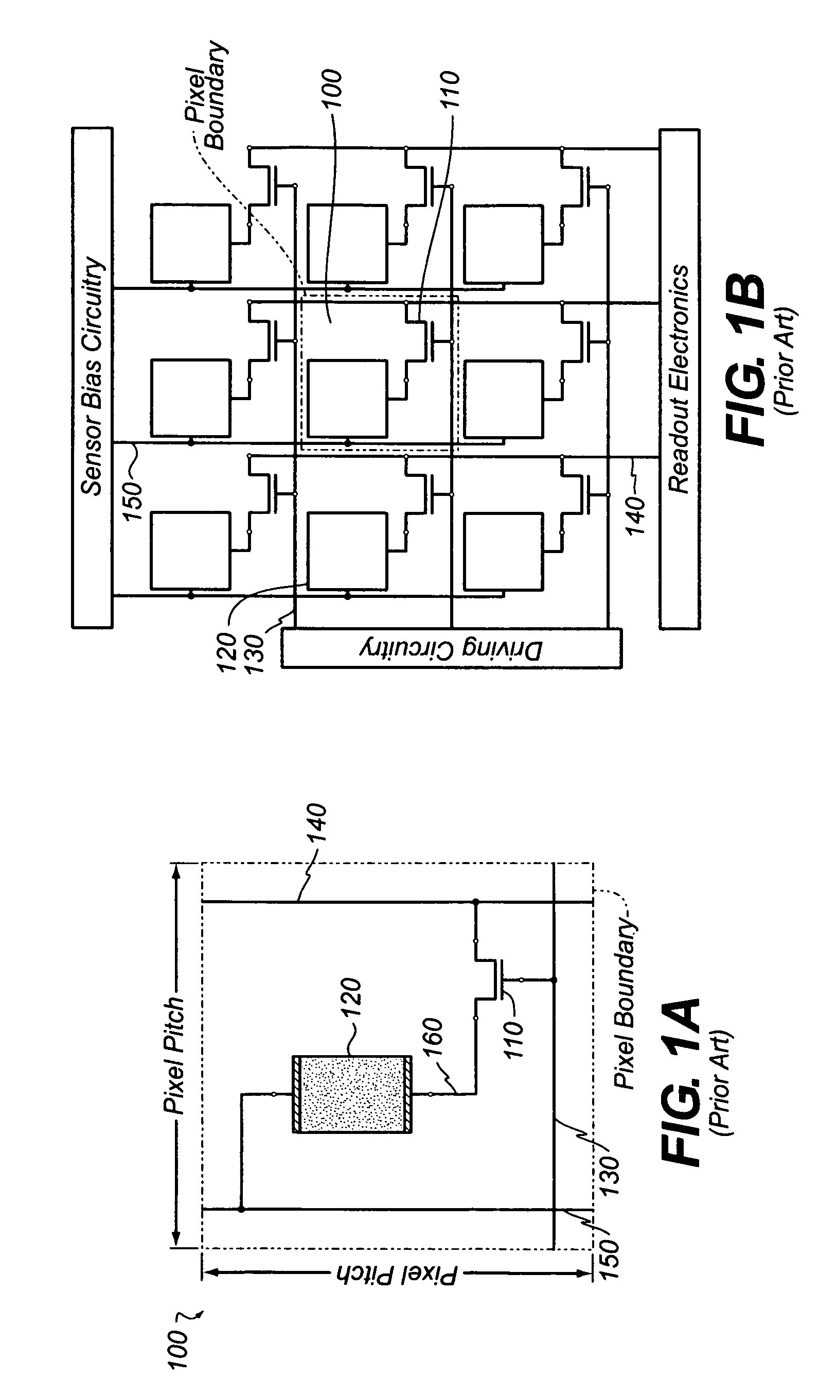
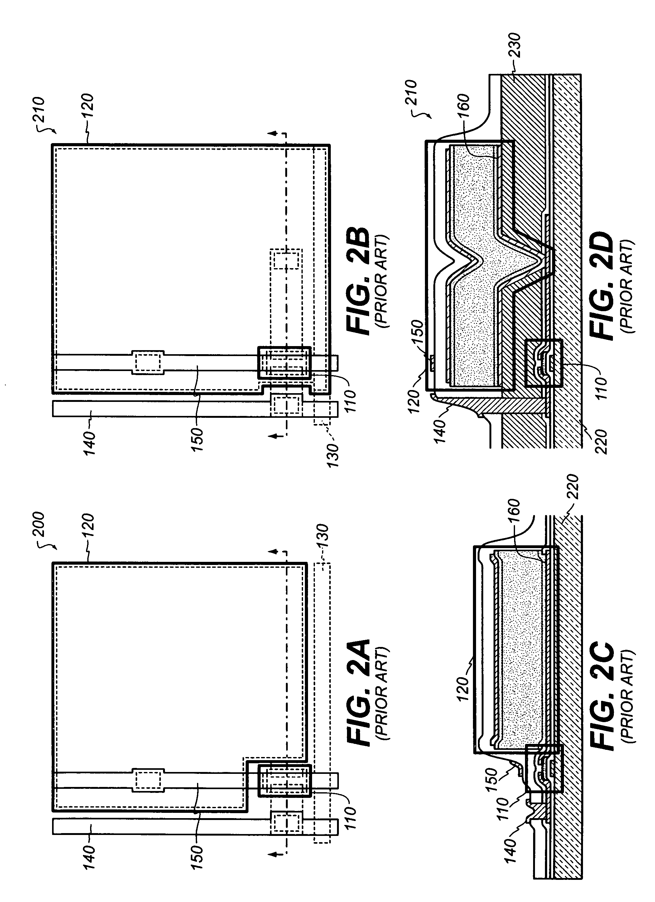
Current optical engine pixel fill factor performance faces several fundamental limitations that prevent achieving the 90% threshold. Traditional silicon-based photodiodes typically achieve fill factors between 60-80% due to inherent structural constraints. The primary limitation stems from the necessary spacing between individual pixels, which includes isolation trenches, metal routing layers, and peripheral circuitry that occupy valuable sensor real estate.
Manufacturing process variations introduce significant challenges in maintaining consistent pixel geometry across large sensor arrays. Photolithography limitations create minimum feature size constraints that directly impact the achievable pixel density. Edge effects at pixel boundaries result in non-uniform electric field distributions, leading to reduced charge collection efficiency in border regions. These variations become more pronounced as pixel sizes decrease to accommodate higher resolution requirements.
Optical crosstalk represents a critical challenge where photons intended for one pixel inadvertently reach adjacent pixels, effectively reducing the useful fill factor. This phenomenon intensifies with smaller pixel pitches and becomes particularly problematic in back-illuminated sensor designs. The refractive index differences between various materials in the optical stack create unwanted light scattering and reflection, further degrading pixel isolation.
Thermal management issues compound these limitations, as increased pixel density generates higher heat loads that can cause performance degradation. Temperature gradients across the sensor array lead to non-uniform dark current generation and sensitivity variations. The thermal expansion mismatch between different materials in the optical engine assembly creates mechanical stress that affects pixel alignment and optical performance.
Electronic noise sources, including read-out circuit interference and power supply fluctuations, impose additional constraints on achievable fill factors. The proximity of digital switching circuits to sensitive analog pixel elements creates electromagnetic interference that degrades signal quality. Power distribution networks require dedicated routing space that competes with active pixel area, creating a fundamental trade-off between electrical performance and optical efficiency.
Packaging constraints further limit fill factor optimization, as wire bonding pads, thermal management structures, and protective coatings consume peripheral space. The mechanical tolerances required for reliable assembly operations impose minimum spacing requirements that prevent maximum theoretical fill factor achievement.
Current Solutions for Maximizing Pixel Fill Factor
01 Microlens array structures for improving pixel fill factor
Microlens arrays can be positioned over pixel arrays to focus incident light onto the photoactive areas of pixels, effectively increasing the optical fill factor. These structures help collect light that would otherwise fall on non-photoactive regions and redirect it to the photosensitive areas, thereby improving light collection efficiency and overall pixel performance.- Microlens array structures for improving pixel fill factor: Microlens arrays can be positioned over pixel arrays to focus incident light onto the photoactive areas of pixels, effectively increasing the optical fill factor. These structures help collect light that would otherwise fall on non-photoactive regions and redirect it to the photosensitive areas, thereby improving light collection efficiency and overall pixel performance.
- Pixel electrode and aperture optimization techniques: The geometric design and arrangement of pixel electrodes and apertures can be optimized to maximize the active area ratio. This involves careful consideration of electrode positioning, aperture size, and the spacing between elements to reduce light blocking and increase the effective light-gathering area of each pixel.
- Advanced photodiode structures and layouts: Specialized photodiode configurations and pixel layouts can enhance fill factor by maximizing the photosensitive area within each pixel. These designs may include optimized junction geometries, improved isolation structures, and novel arrangements that minimize dead space while maintaining electrical performance and reducing crosstalk between adjacent pixels.
- Color filter and light management integration: Integration of color filters with optimized light management structures can improve pixel fill factor by enhancing light transmission and reducing optical losses. This approach involves coordinating the design of color filter arrays with underlying pixel structures to maximize light coupling efficiency and minimize reflection losses at interfaces.
- Backside illumination and through-silicon via technologies: Backside illumination architectures combined with through-silicon via connections can significantly improve fill factor by eliminating front-side metal routing that blocks incident light. This technology allows for larger photoactive areas by moving interconnects to the back of the device, enabling higher quantum efficiency and improved optical performance.
02 Pixel architecture optimization for enhanced fill factor
The physical design and layout of pixel structures can be optimized to maximize the photoactive area relative to the total pixel area. This involves minimizing the space occupied by control circuitry, interconnects, and other non-photoactive elements while maintaining proper pixel functionality and signal quality.Expand Specific Solutions03 Light guide and waveguide integration
Integration of light guide structures and waveguides within the optical engine can improve light collection and distribution across the pixel array. These structures help channel light more efficiently to the photoactive regions and reduce optical losses, particularly important in compact optical engine designs where space constraints limit conventional optical elements.Expand Specific Solutions04 Anti-reflective coatings and optical interface optimization
Application of specialized coatings and optimization of optical interfaces can reduce reflection losses and improve light transmission to the pixel array. These techniques help maximize the amount of incident light that reaches the photoactive areas, effectively increasing the optical fill factor through improved light coupling efficiency.Expand Specific Solutions05 Color filter and spectral optimization techniques
Advanced color filter designs and spectral optimization methods can improve the effective fill factor by enhancing the spectral response and light transmission characteristics of the pixel array. These approaches focus on maximizing the useful light collection while maintaining proper color separation and spectral accuracy in the optical engine.Expand Specific Solutions
Key Players in Optical Engine and Pixel Technology
The optical engine pixel fill factor enhancement market represents a mature yet rapidly evolving sector driven by increasing demand for high-resolution displays and advanced imaging systems. The industry has reached a critical growth phase with market expansion fueled by applications in smartphones, automotive displays, AR/VR devices, and professional imaging equipment. Technology maturity varies significantly across key players, with established leaders like Samsung Electronics, Sony Group, and Canon demonstrating advanced capabilities in sensor design and manufacturing processes. Display manufacturers including BOE Technology, Samsung Display, and TCL China Star are pushing boundaries in panel optimization, while semiconductor foundries such as ASML Netherlands, SMIC, and Shanghai Huali Microelectronics provide essential fabrication technologies. Emerging players like OmniVision Technologies and OM Digital Solutions are contributing specialized imaging solutions, creating a competitive landscape where achieving above 90% fill factors requires sophisticated pixel architecture design, advanced lithography processes, and innovative materials engineering across the entire supply chain ecosystem.
ASML Netherlands BV
Technical Solution: ASML provides advanced lithography equipment and processes that enable semiconductor manufacturers to achieve pixel fill factors above 90% through extreme ultraviolet (EUV) lithography technology. Their systems enable precise patterning of photodiodes and metal interconnects with sub-10nm resolution, allowing for optimized pixel layouts that maximize photosensitive area. ASML's immersion lithography and computational lithography solutions help foundries implement advanced pixel designs with minimal dead space between photodiodes. Their technology roadmap supports continued scaling to smaller pixel pitches while maintaining high fill factor performance through improved overlay accuracy and pattern fidelity.
Strengths: Market-leading lithography technology essential for advanced pixel manufacturing, critical enabler for next-generation sensor production. Weaknesses: Equipment supplier rather than direct sensor manufacturer, extremely high capital costs for EUV systems limiting accessibility.
Samsung Electronics Co., Ltd.
Technical Solution: Samsung utilizes advanced ISOCELL technology with deep trench isolation and optimized pixel structure design to achieve fill factors exceeding 90% in their CMOS image sensors. Their approach incorporates innovative metal grid barriers between pixels and enhanced microlens technology that improves light collection efficiency. The company's dual conversion gain technology and tetracell pixel binning methods enable higher effective fill factors while maintaining excellent low-light performance. Samsung's latest 0.7μm pixel technology demonstrates fill factors reaching 93% through advanced semiconductor fabrication processes and optimized photodiode geometry.
Strengths: Large-scale manufacturing capabilities with advanced semiconductor processes, integrated supply chain from sensors to displays. Weaknesses: Intense competition in mobile sensor market, high capital investment requirements for next-generation facilities.
Core Innovations in 90%+ Fill Factor Technologies
Methods and apparatus for high fill factor and high optical efficiency pixel architecture
PatentInactiveUS20140009731A1
Innovation
- The design incorporates a reflector with through-holes instead of gaps, allowing for a higher fill factor by minimizing the non-reflective areas and using a transparent dielectric layer to electrically isolate pixel electrodes, while optimizing the thickness and refractive index of the dielectric layer for maximum reflectivity across the visible spectrum.


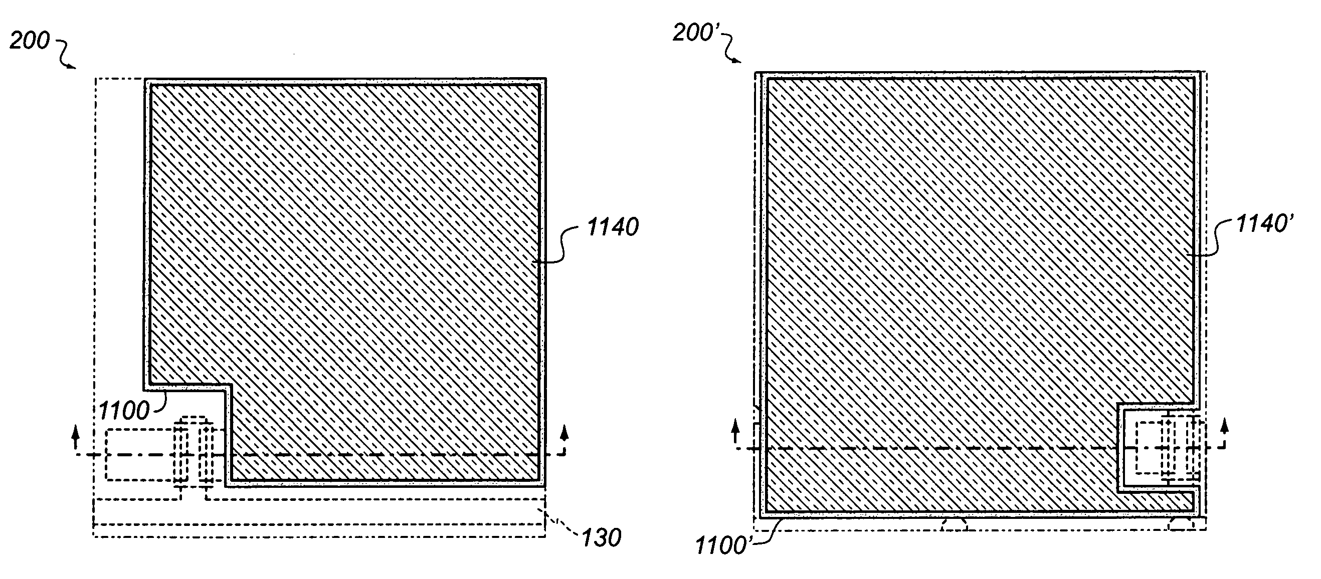
Coplanar high fill factor pixel architecture
PatentInactiveUS7902512B1
Innovation
- The design includes a pixel architecture with a scan line and bias line configuration that allows for a higher fill factor by optimizing the placement and routing of these lines, using a wider bias line and additional metal layers to reduce capacitance coupling and enhance thermal dissipation, while maintaining or improving signal quality.

Manufacturing Process Optimization for Fill Factor
Manufacturing process optimization represents a critical pathway for achieving pixel fill factors exceeding 90% in optical engines. The precision of semiconductor fabrication processes directly impacts the geometric arrangement and functional area utilization of individual pixels within the optical array structure.
Advanced lithography techniques form the foundation of fill factor enhancement. Implementing extreme ultraviolet (EUV) lithography enables sub-10nm feature resolution, allowing for more precise pixel boundary definition and reduced inter-pixel spacing. The adoption of multiple patterning techniques, including self-aligned double patterning (SADP) and self-aligned quadruple patterning (SAQP), facilitates the creation of denser pixel arrays while maintaining structural integrity and optical performance.
Etching process refinement plays a pivotal role in maximizing active pixel area. Atomic layer etching (ALE) provides unprecedented control over material removal, enabling the creation of vertical sidewalls with minimal tapering. This precision reduces the dead space between adjacent pixels and allows for larger photoactive regions within each pixel cell. Plasma etching parameter optimization, including gas chemistry selection and RF power modulation, further enhances etch selectivity and profile control.
Deposition process improvements contribute significantly to fill factor optimization. Atomic layer deposition (ALD) enables conformal coating of complex three-dimensional structures, ensuring uniform material properties across the entire pixel array. Chemical vapor deposition (CVD) process tuning allows for gap-fill optimization in high-aspect-ratio structures, reducing void formation that could compromise pixel performance.
Wafer-level packaging integration represents an emerging approach to fill factor enhancement. Through-silicon via (TSV) technology enables vertical interconnection schemes that eliminate traditional wire bonding requirements, reducing peripheral dead space. Advanced flip-chip bonding techniques with micro-bump pitches below 20μm facilitate higher interconnection density while maintaining optical path integrity.
Process monitoring and control systems ensure consistent manufacturing outcomes. Real-time metrology integration, including scatterometry and ellipsometry, provides immediate feedback for process parameter adjustment. Statistical process control implementation maintains tight tolerances on critical dimensions, ensuring reproducible fill factor performance across production batches.
Cost-Performance Trade-offs in High Fill Factor Systems
Achieving pixel fill factors above 90% in optical engines presents significant cost-performance trade-offs that must be carefully evaluated across multiple dimensions. The pursuit of ultra-high fill factors typically requires advanced manufacturing processes, premium materials, and sophisticated optical designs that substantially increase production costs while delivering diminishing returns in performance improvements.
Manufacturing complexity escalates dramatically when targeting fill factors exceeding 90%. Advanced lithography techniques, precision alignment systems, and specialized fabrication equipment become necessary, often doubling or tripling production costs compared to conventional 80-85% fill factor systems. The yield rates also decrease significantly due to tighter tolerances, further impacting overall cost-effectiveness.
Material selection represents another critical cost driver in high fill factor implementations. Premium optical materials with superior refractive indices and lower dispersion characteristics command substantial price premiums. Additionally, specialized coatings and substrates required for minimizing optical losses can increase material costs by 150-300% compared to standard alternatives.
Performance gains from achieving 90%+ fill factors show logarithmic rather than linear improvements. While the jump from 70% to 85% fill factor provides substantial brightness and efficiency enhancements, the incremental benefit from 85% to 95% becomes progressively smaller. This diminishing return pattern challenges the economic justification for extreme fill factor optimization.
System-level considerations further complicate the cost-performance equation. High fill factor optical engines often require enhanced thermal management systems, more sophisticated control electronics, and improved mechanical stability, adding 20-40% to overall system costs. The reliability implications of operating at these performance extremes may also necessitate redundant components or over-engineering of supporting subsystems.
Market positioning becomes crucial when evaluating these trade-offs. Premium applications in aerospace, medical imaging, or high-end projection systems may justify the cost premium for marginal performance gains. However, consumer electronics and mainstream commercial applications typically cannot absorb the additional costs without compromising market competitiveness.
The optimal balance point for most applications appears to be in the 88-92% fill factor range, where reasonable cost increases still deliver meaningful performance improvements without entering the steep cost escalation zone of ultra-high fill factor designs.
Unlock deeper insights with PatSnap Eureka Quick Research — get a full tech report to explore trends and direct your research. Try now!
Generate Your Research Report Instantly with AI Agent
Supercharge your innovation with PatSnap Eureka AI Agent Platform!